Scheppach HF-50 Spindle Moulder

The Scheppach HF-50 Spindel Moulder/ Router Table. Photo: Scheppach

In North America, a table saw is often used to cut dados (square sectioned grooves). A stacked dado blade set is a sandwich of blades to be fitted onto a table saw for making dados and rabbets. There are two rim (outer) blades. These differ from each other and are referred to as the left rim and the right rim blade, respectively. There is also a series of chippers, specially-designed blades that fit between the rim blades, as well as dado shims aka spacers, that lack any cutting features, but vary in thickness. They can be made of metal or plastic. These ensure that the dado is the precise width that is needed.

The arbour (the axis or shaft that supports and rotates the blades of a table saw) has to be long enough to accommodate the stacked dado blade set. This is the challenge with European table saws. Their arbours are too short to accommodate more than a single blade, and still allow the nut to be fully threaded onto the arbour when the blade is tightened. Thus, making dados is a task that is normally done with some form of router in Europe. The main problem with this approach is that there are is not an unlimited choice of router bits to select from.

While most routers are portable machines, something approaching a table saw is also available, but with a rotating vertical shaft, rather than a horizontal shaft. The spindle moulder (British English)/ wood shaper (American English)/ router table (General) comes with a motor, frequently housed below the table surface.

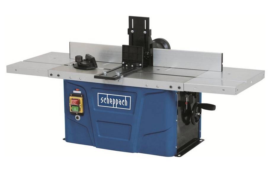
The Scheppach HF-50 is a machine for DIY enthusiasts, rather than professionals. The author’s many different Scheppach tools, were all purchased for work on a house renovation project, and are not intended to be kept beyond its completion. These are not especially durable machines. The main reason the HF-50 was purchased, was the lack of choice. Professional machines cost five times more than the NOK 3 300 (USD 300) spent, and at least twice as much used. The HF-50, and many other machines, will be replaced by the end of 2023 with a CNC machine, probably with a router as well as laser cutter. It may even include a plasma cutter. Such a machine costs about 20 times the price of a router table, but will provide greater production flexibility.

In contrast to a router, stock (the unprocessed wood) runs along a vertical fence from right to left. Viewed from in front of the infeed, the cutter head can be described as a right-hand vertical side head. Other configurations include a bottom horizontal head, a left-hand vertical side head, and a top horizontal head. A single head moulder will only cut one surface at a time. It is common for multi-head moulders to have up to four heads.

The spindle is height adjustable from 0 to 40 mm. While most spindle moulders rotate between 3 000 and 10 000 rpm, the HF-50’s speed varies from 11 500 to 24 000 rpm, close to that found on a portable router. The cutters shanks have a diameter of 6 mm / 8 mm / or 12 mm. Power on the HF-50 comes from a 1 500 W motor. Other spindle moulders may have as little as 750 W, to as much as 5 000 W per head.

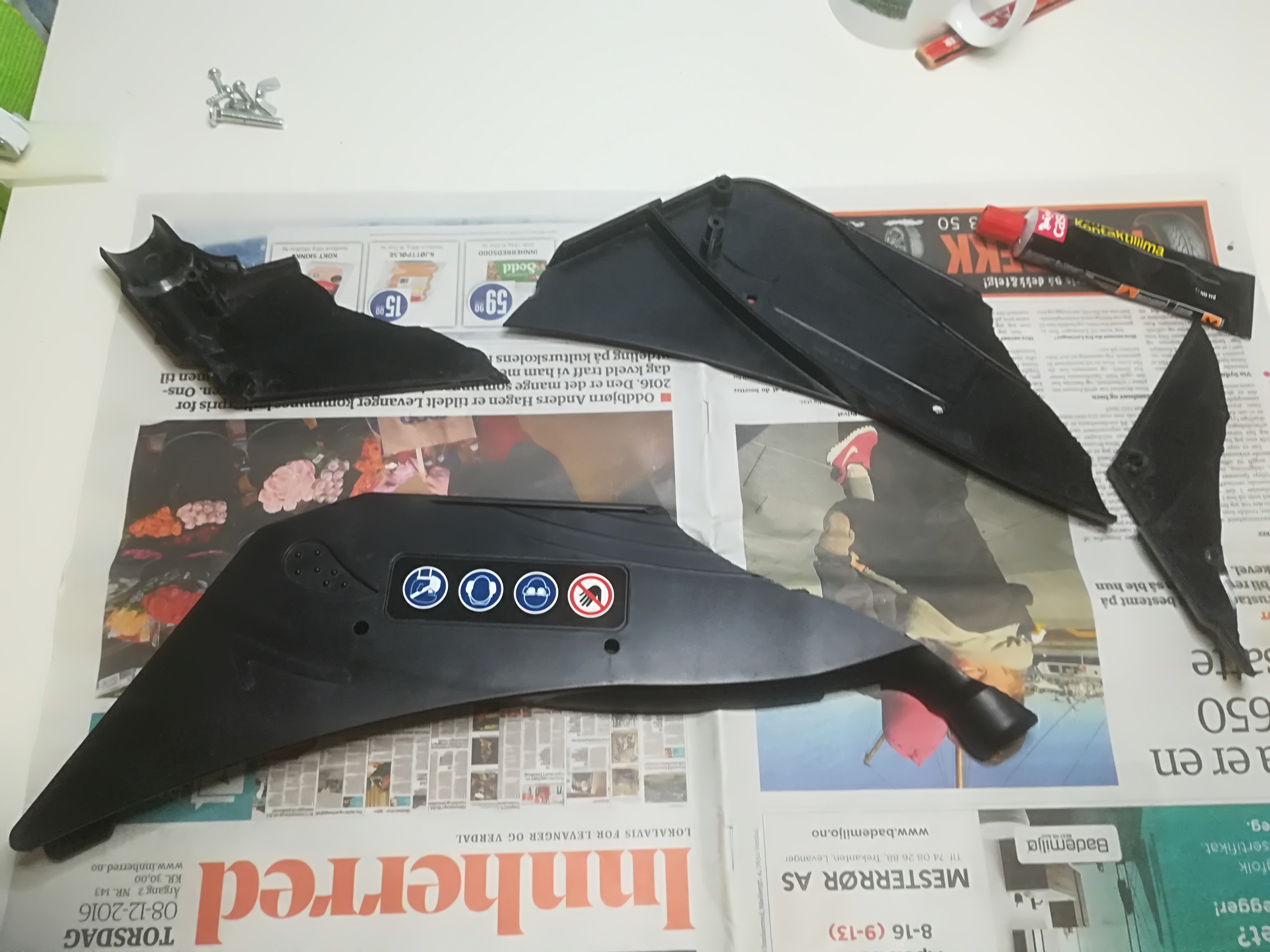
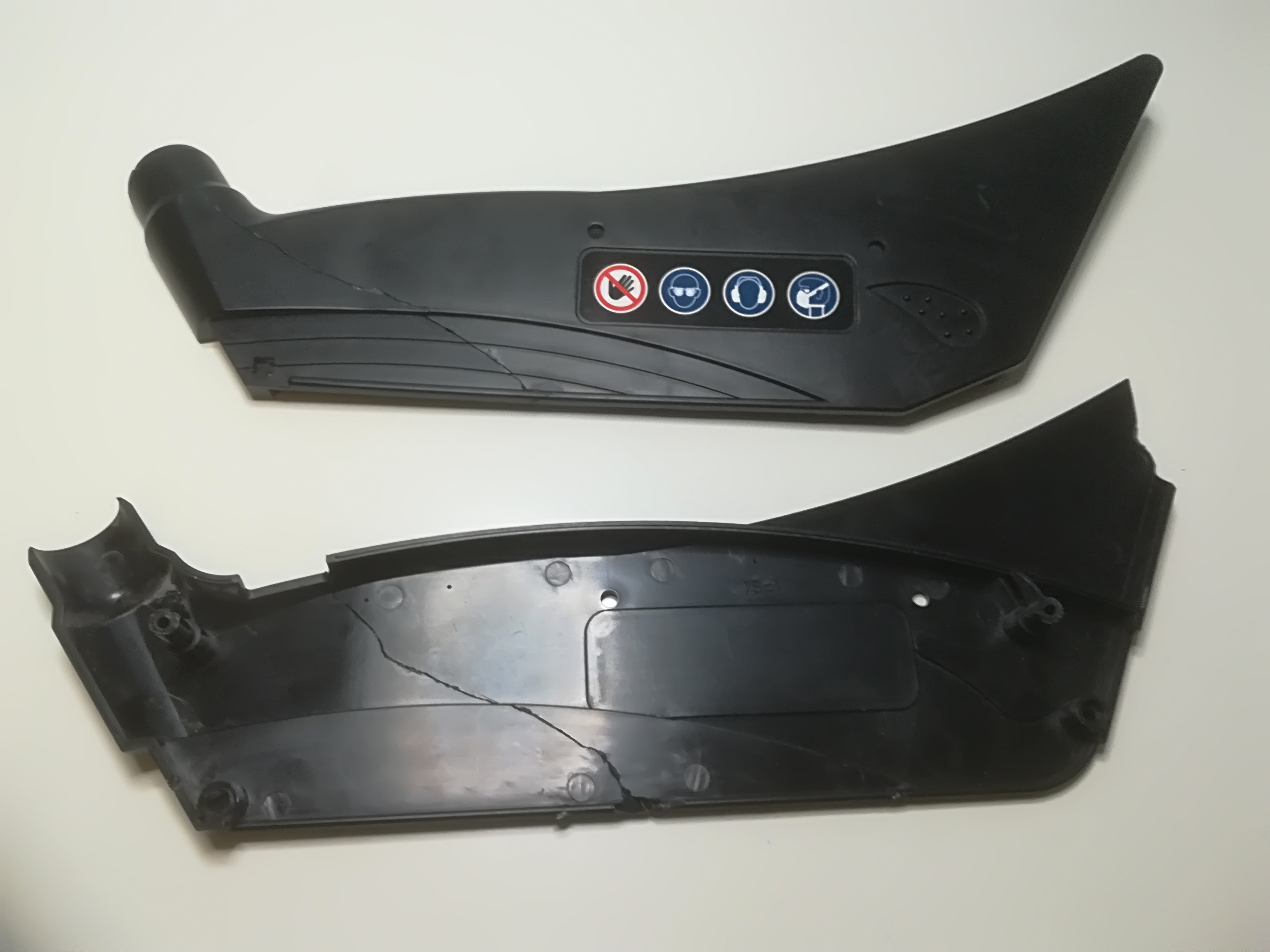
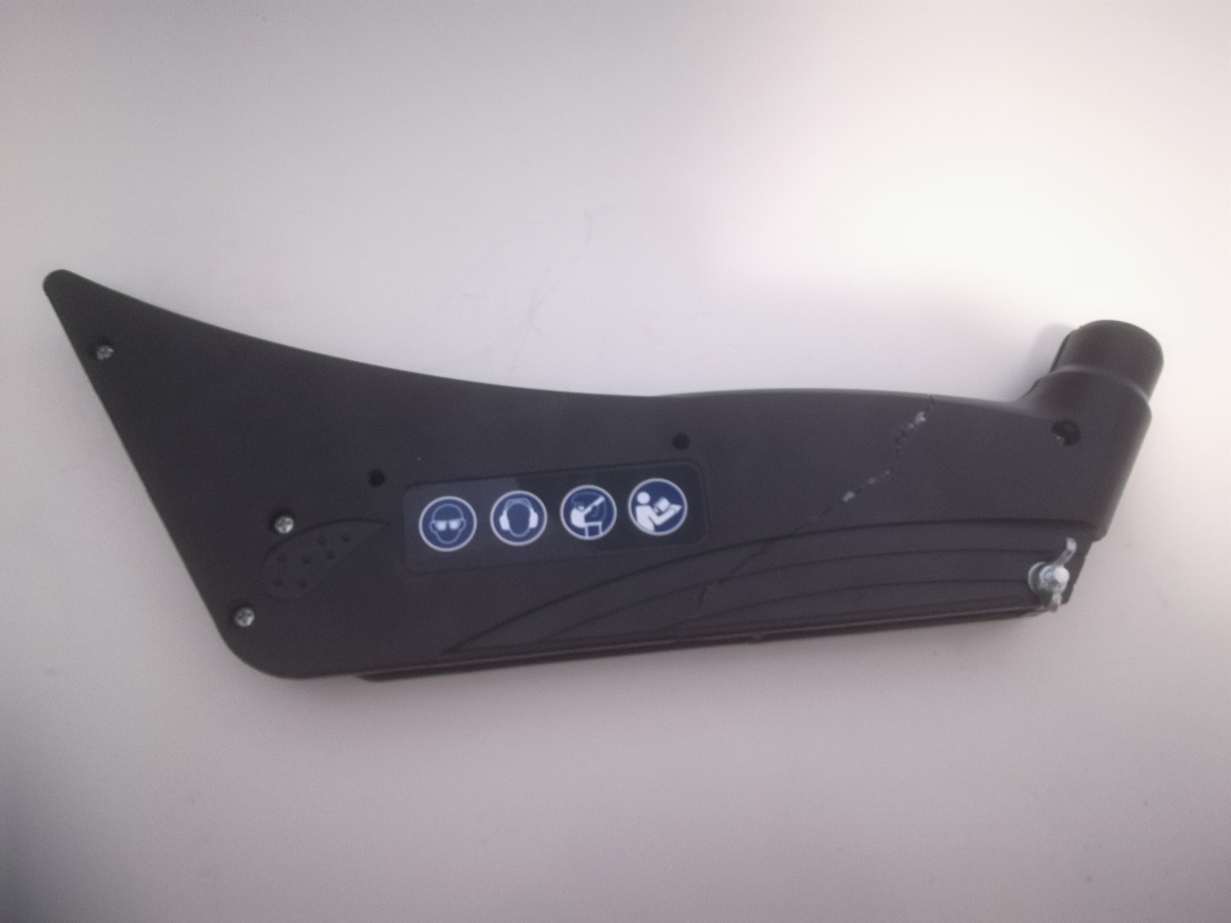
Hearing, eye and respiratory protection are necessary when using a spindle moulder. The machine itself is usually equipped with a guard above the cutter, to protect hands and prevent garments from being drawn into its blades. Hold-downs and feather-boards can also prevent injury.

There are two major jobs intended for the spindle moulder. The first is to use it to make drawers for kitchen cabinets. This will follow some of the advice of John Heisz in his video, How to Make Drawers the Easy Way, with additional information provided by Gary Katts in the video, The Quarter-Quarter-Quarter Drawer System. Quarter inch is translated as 6 mm.

The second is to make moulding that for LED strip lighting, that will be covered with translucent plexiglas. This is a relatively simple design, that will allow much of the house lighting to be DC powered. Electricity will be supplied using Power over Ethernet (PoE) standards. PoE cables are in place throughout the house.

In addition, I intend to make an oak table from counter-tops. Since the width of the table is 900 mm, while a counter-top is 600 mm, this means two edges will have to be planed, using a spindle moulder, rather than a jointer. This eliminates one more tools from the workshop, saving space.

After these three projects are completed there will undoubtedly be other projects that will use the capabilities of a spindle moulder.

Note: This post was originally started 2018-03-18 15:23:25. Its original title was Workshop Tools: Shaper.

Whetstone Sharpener: A tidbit

A Scheppach TiGer 2000 Whetstone Sharpener. Photo: Scheppach.

At my local hardware store (Jula), there are electric grinding stones in all price categories from NOK 250 to 3 200 (USD 32.50 to 416). I paid NOK 1 500 (USD 195) for mine. Why this price difference?

Depending on your worldview, the Rolls-Royce, Maybach, Cadillac, Zil, Toyota Century or Trek (yes, the bicycle) of the grindstone world is Tormek, a Swedish manufacturer. If you want to be convinced that one should spend more money on a whetstone sharpener, there is a YouTube video that explains everything, Why does the Tormek T-7 and T-4 cost so much? Interview and review with Stig from Sweden: https://www.youtube.com/watch?v=ESW3wy0PI18

Not being convinced, I opted for a Scheppach TiGer 2000 S, which looks like a plagiarized version of the Tormek T4. The T4 is undoubtedly better. One person suggests 20% better, whatever that means. It also comes with a 7 year guarantee.

While larger diameter grindstones are preferred to this 200 mm machine, because they provide a larger concave grind on edge tools, these larger machines also need a more powerful motor and housing, making them more expensive.

While the unit comes with both a straight jig and an angle guide, some users may want to invest in a wheel dressing jig to flatten/ true the stone edge. Specialist jigs are available for knives, woodturning tools, axes and scissors.

Mount the stone wheel and plugging it in, is all that is needed to set up the machine. The metal shaft is strong. However, the sharpening jig fits loosely. Many reviewers have commented that a Tormek jig is much better. The 120 W motor is more than adequate. Most tools can be ground adequately. The leather honing wheel is also adequate.

Note: The first three paragraphs of this tidbit were originally written: 2018-03-18 at 07:15:29 with the title Workshop Tools: Whetstone Sharpener. Since then it has been waiting for further inspiration, that has never arrived. On 2020-03-08 at 23:00 the text was edited into blocks using the new(ish) Gutenberg block editor, rather than the Classic editor used in 2018. The title was changed to Whetstone Sharpener: A tidbit. The last three paragraphs were added, along with an illustration of the Scheppach TiGer 2000. Prices in NOK were identical in 2018-03 and 2020-03. However, the Tormek had increased its price to NOK 3 800. In 2020, 1 USD is worth almost 10 NOK, this will also influence price comparisons.

Workshop Tools: Electric Plane

A plane is a tool for shaping and smoothing wood. In the pre-industrial period hand planes were used to flatten, reduce the thickness of, and dress (smooth) rough lumber. Most of this work is now done by electric planers (aka thicknessers). Special types of planes were also used to cut joints or mouldings. A typical example is the rabbet plane. Today, a router or shaper is used for this work, although – increasingly – specialized tools are used.

In a workshop, the most important use of a plane was to integrate surfaces on workpieces. It is here that the electric plane has taken over, although it is unsuited for many delicate jobs that must still be entrusted a manual plane.

An electric plane is a portable machine that uses rotating knives to smooth a surface. The main reason for using an electric plane is to save time, “In  1918 an air-powered handheld planing tool was developed to reduce shipbuilding labor during World War I. The air-driven cutter spun at 8000 to 15000 rpm and allowed one man to do the planing work of up to fifteen men who used manual tools.” https://en.wikipedia.org/wiki/Plane_(tool) referencing Planing Ship Timbers with Little Machines, Popular Science monthly, December 1918, page 68, Scanned by Google Books: https://books.google.com/books?id=EikDAAAAMBAJ&pg=PA68

bmd
Meec Electric Plane

Yesterday, was the first time that I have used an electric plane. It is considerably heavier than the manual jack plane that I am used to. While not absolutely necessary, its operation feels better using two hands. It was used to trim MDF board so the same dimensions as the frame underneath. This is not a task that I would even contemplate with a manual plane. One could argue that an electric plane is not essential for this task. An alternative approach would be to use a router with a flush trimming bit. The challenge, in Norway, is that it is impossible to get 50 mm bits. So, in reality there is no alternative to an electric plane.

At the moment I have not had to sharpen the plane knives, although using them on MDF will require them to be sharpened soon.

I have no complaints with the Meec plane. It is solidly built but heavy, weighing 3 kg, despite an aluminum base plate. It offers 900 W of power, with a knife width of 82 mm, allowing it to cut from 0 to 2.5 mm in depth. It operating speed is 16 000 rpm. Unlike many other electric planes, this uses 3 double-edged knives. This means that the knives are reversible. The plane is equipped with a dust port that can be connected to the shop dust extraction system. It came with a parallel guide and a depth guide, as well as a dust bag and an extra drive belt. It cost NOK 600 (USD 78).

In comparison, a Bosch PHO 2000 electric plane has 680 W of power, the same knife width (82 mm), but a maximum cutting depth of 2.0 mm. It weighs 2.4 kg. The Bosch operates at a higher speed, 19 500 rpm. It provides only 2 knives, but they are easier to remove. At NOK 1 200, it costs twice the price of the Meec.


Workshop Tools: Hammer Drill

On 24 June 1996, I purchased a Black & Decker electric drill. Tools at the time were much more expensive than today. This drill cost over NOK 1 000 (USD 200). Until now, I have been happy with that purchase, and the drill works well even after more than 20 years of use. My wife fondly remembers using this drill to screw in all of the boards on the sun deck. Today, this faithful tool was transferred from the workshop to assume new, and less demanding, duties in the house.

bmd
Black & Decker Hammer Drill from 1996. It cost over NOK 1 000 (USD 200).

The main problem with this drill is not its colour, or its age. It is its lack of power. With only 450 W it is unable to do the work required of a drill in the workshop. Constructing work benches, I have to connect 48 x 96 mm boards with almost 100 each of 5.0 x 90 mm screws, and 6.0 x 160 mm screws. Both types are self-tapping production screws. The B&D was unable to drive the screws in without pilot holes. Even then, it would stop, refusing to move forward, so that an old man could demonstrate his strength driving the screws home, by hand.

On Wednesday, 7 March 2018, a replacement drill was purchased. It is a Meec Red 000 110 hammer drill. It cost NOK 600 (USD 77). It provides 1 150 W of power. Two other differences are: 1) a keyed chuck, and 2) two gears. Otherwise, both are functionally very similar.

bty
Meec Red Hammer Drill, new in 2018. It cost NOK 600 (USD 77).

The advantages of using this hammer drill were immediately apparent. First, compared to a key-less chuck, a keyed chuck is able to hold drill bits more securely, and it is easier to release them again. Second, rather than attaching masking tape onto a drill bit, it provides a depth gauge attachment. Third, it comes with a grip, so that both hands can be used to hold onto the tool. A related disadvantage is that this new drill is considerably heavier, so there is a greater need for a grip.

This drill was able to take advantage of the self-tapping screws, and was able to power them completely in. There was no need for any pilot holes. In general, this drill seems to be capable of providing the power a portable workshop drill needs.


Getting started …

with workshop activism.

wooden spatula

This post is especially for three ladies who have been subjected to lofty ideas about making geodesic dome greenhouses, when all they really wanted was to learn how to make a wooden spatula.

Minni, the minimalist maker from Finland, shows them how to do it in a three minute video: https://www.youtube.com/watch?v=sZZtGSctCUw

MATERIALS: Wood (Minni uses alder), painter’s tape

TOOLS: Pen, spatula template, band saw, belt sander, sandpaper

USEFUL TIPS: After sanding, wet the spatula to raise the wood grain. Let dry, and sand again. This makes the surface very smooth.

SAFETY NOTES: Safety first! Always be careful with dangerous tools and make sure you know how to use them correctly.

MUSIC BY Henbrix

Here is the spatula template from her website: https://theminimalistmaker.com/shop/7k7o6c3lkngpjisbi7cyc0e41xg9vt

The Unit One work space has a band saw as well as a belt sander. There is an alder tree on the property, but it is too young and small to be used to make spatulas.

Workshop Layout: Machine Alley

In this Workshop Layout series, I will periodically look at the various machines at the Unit One workshop at Ginnunga Gap, and commenting on some of their features, the challenges of using them, in terms of workshop location. In this first post, attention will be focused on the placement of a rip saw (aka table saw), as its position affects almost everything else.

Being a workshop owner is much like being a kennel owner. The first question begging to be answered is, Who is the owner? Is it a person? Or is it the dogs/ machines? Today, the dogs/ machines may lack legal ownership, but they seem in control. The reason for this is the lack of workshop space to handle materials exceeding  about 2 400 mm in length.

hs105_ha
Scheppach HS105 rip saw (table saw), in the same orientation as visitors will see it entering the Unit One workshop at Ginnunga Gap.

There have been four variations of a single workshop design made for Unit One, with machines along one wall, Machine Alley. These are Workshop 1.0, 1.1, 1.2 and 1.3. In all of these versions, the rip saw’s arbor is positioned at the halfway point of the length of the workshop. The workshop is slightly over 6 meters in length. With the arbor half-way, sheet goods, typically 2.4 meters long, can be positioned on the in-feed table, then fed through the saw to the out-feed table, without having to move machinery.

The basic design of Workshop 1.0 and 1.1 were identical, but with two pieces of equipment changing places. At this stage of development, every piece of equipment was assigned a width of 600 mm, with the exception of the rip-saw (previously referred to as the table saw), which was given 1 200 mm. The basic design was made without any equipment having been purchased. Feed direction was ambiguous in the first design.

bty
Workshop versions 1.0 & 1.1. The only differences are related to which tools are assigned to which slots. The other major decision is to have the workbench against the window wall. There is no indication of rip saw feed in the drawing.

Equipment placement in version 1.1 and 1.2 (in parenthesis where it differs from 1.1): 1 = band saw; 2 = router table; 3 = cross-cut saw, previously referred to as a mitre saw; 4 = planer (drill stand); 5 = jointer; 6 = drill stand (planer); 7 = sander.

With version 1.2 the jointer was removed from the workshop, because it was decided that its work (edge planing) could be performed with a router table, provided that router table was made or purchased with separately adjustable split fences. The main reason why both the joiner and the planer were initially placed in the back half of the workshop was because that made them closer to the dust extractor. With rip saw in-feed at the back of the workshop, the rip saw fence would have been positioned along the wall of machine alley.

signal-2018-02-08-230731.jpeg
Workshop design 1.2 made after a Scheppach HS105 rip saw was purchased. The main deviation with respect to earlier versions is the width assigned to the rip saw, which is 900 mm. With Machine Alley at the top of the drawing, work flow is from right to left, as indicated by the arrow.


bty

Currently, workshop design 1.3 is used for operational decisions. This changes the direction of feed, and changes the position of the rip saw fence to the middle of the workshop. In-feed is improved when the router table, aka shaper or spindle molder is co-located with the in-feed, and more poorly served when a cross-cut saw (aka chop saw, or sliding compound mitre saw) is on the in-feed side. Working sheet materials around a cross-cut saw is much more difficult than having to deal with a router table.

Machine Alley now has the band saw moved adjacent to the entry doors, then comes about 1150 mm of space that can be used for hand tools, portable electric tools and air tools. This is followed by the router table, rip saw and cross-cut saw, previously discussed. Another 1480 long space follows, part of the out-feed area that can be used for sub-component and smaller project assembly. At a future date, this area can be re-purposed to serve as a location for a wood lathe, removing it from its previous proposed location along the back wall. The drill press is located at  the far end of the wall.

The planer, previously given a permanent position, is now regarded as a machine that only requires temporary placement.

Conclusions

While I would have liked to have had the dust extraction system, air lines and even workbenches to be in place, I am very happy that the three first iterations were not implemented. Procrastination has its benefits. The failure to implement the initial design has saved me from having to rip out components and start over, or to accept an inferior design.

All cutting machines, stationary as well as portable, are now all placed on Machine Alley. This simplifies dust extraction.

Plastic tablesaw blade guards

Cheap table saw blade guards are seldom worth the plastic they are made of.

One reviewer suggested that potential purchasers of table saws should disregard the saw blade guards that come with the machines. They will probably have to be replaced with more appropriate equipment. Recently, I was happy to have been given that advice. When a 25 kg sheet of Baltic birch plywood crashed into my guard it shattered, with two large broken pieces the result.

A temporary repair involved the disassembly of the two main plastic parts. Contact cement was then used to glue each broken pieces to its main piece. Finally, the two main parts were assembled again. If this guard is ever used again, it will be further reinforced with duct tape. While the repairs were being made, I was building the next iteration of a saw blade guard in my mind.

bty
Here are the four pieces of the broken saw blade guard, along with the screws used to hold each half of the guard together.
bty
The pieces after being glued together with contact cement.
bmd
The reassembled saw blade guard.

The guard was actually not fit for purpose. While the guard had its own connection to the dust collector, it was unable to accommodate sheets of plywood because its hose was in the way. Thus, I had to disconnect the hose while cutting the plywood.

Marmot is the brand name of products I make for my own personal enjoyment. During the design process of the saw blade guard, I made 4 iterations of the design, designated V (for version) 1 to 4.

V1

guard-wood-v1.jpeg

V1 is conceptually the same guard as the original Scheppach guard, but made with 12 mm Baltic birch plywood. The version was made just before I went off to sleep for the night.

V2

bty

In the morning, when I awoke, I knew there were two changes that had to be made to the guard. The first was the use of 6 mm Baltic birch plywood for the side pieces. This reduced the width of the guard by 12 mm. The second was a repositioning of the dust extractor. It now exits the guard horizontally, rather than vertically.

V3

bty

Here the main change was the orientation of the drawing. In terms of materials, I tried to take advantage of the irregular size of Baltic birch plywood. Its sheets are 1220 mm x 2440 mm. When making 600 mm oriented products, this leaves lengths of 20 mm plywood and widths of 40 mm plywood as waste. In this case, this waste can be used to make some of the structural components for the guard, in particular those coloured green in the drawings. No sooner had I made the drawing, than I noticed a logical flaw, which necessitated another version, V4.

V4

bty

To save time, I got out my light table. which made redrawing faster, but slightly less accurate than using a pencil, eraser and ruler. The logical error involved the thickness of the orange pieces in V4. These are 6 mm in V4, but 12 mm in V3. These pieces originate in the isosceles right triangles removed from the front of the 300 x 110 mm rectangular sides. These have a side length of 90 mm, and a hypotenuse length of 127 mm.  Each of these triangles has two additional isosceles right triangles removed to be used to strengthen the front of the guard. Their side lengths are 25 mm, with a hypotenuse length of 35 mm.

The next step will to actually build the saw blade guard, and to test it out.

This weblog post was updated 2021/12/21. to eliminate Weeds from the title. This post formed part of a Needs, Seeds and Weeds website that belonged to my daughter, Shelagh. In addition, other things are also out of date, or my opinions have changed. Apart from the title, updating the text to a block format and other minor formatting changes, the text above this paragraph remains as it was before. Any significant content changes are found below this paragraph