In this Workshop Layout series, I will periodically look at the various machines at the Unit One workshop at Ginnunga Gap, and commenting on some of their features, the challenges of using them, in terms of workshop location. In this first post, attention will be focused on the placement of a rip saw (aka table saw), as its position affects almost everything else.
Being a workshop owner is much like being a kennel owner. The first question begging to be answered is, Who is the owner? Is it a person? Or is it the dogs/ machines? Today, the dogs/ machines may lack legal ownership, but they seem in control. The reason for this is the lack of workshop space to handle materials exceeding about 2 400 mm in length.
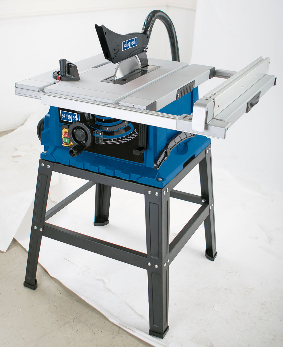
There have been four variations of a single workshop design made for Unit One, with machines along one wall, Machine Alley. These are Workshop 1.0, 1.1, 1.2 and 1.3. In all of these versions, the rip saw’s arbor is positioned at the halfway point of the length of the workshop. The workshop is slightly over 6 meters in length. With the arbor half-way, sheet goods, typically 2.4 meters long, can be positioned on the in-feed table, then fed through the saw to the out-feed table, without having to move machinery.
The basic design of Workshop 1.0 and 1.1 were identical, but with two pieces of equipment changing places. At this stage of development, every piece of equipment was assigned a width of 600 mm, with the exception of the rip-saw (previously referred to as the table saw), which was given 1 200 mm. The basic design was made without any equipment having been purchased. Feed direction was ambiguous in the first design.
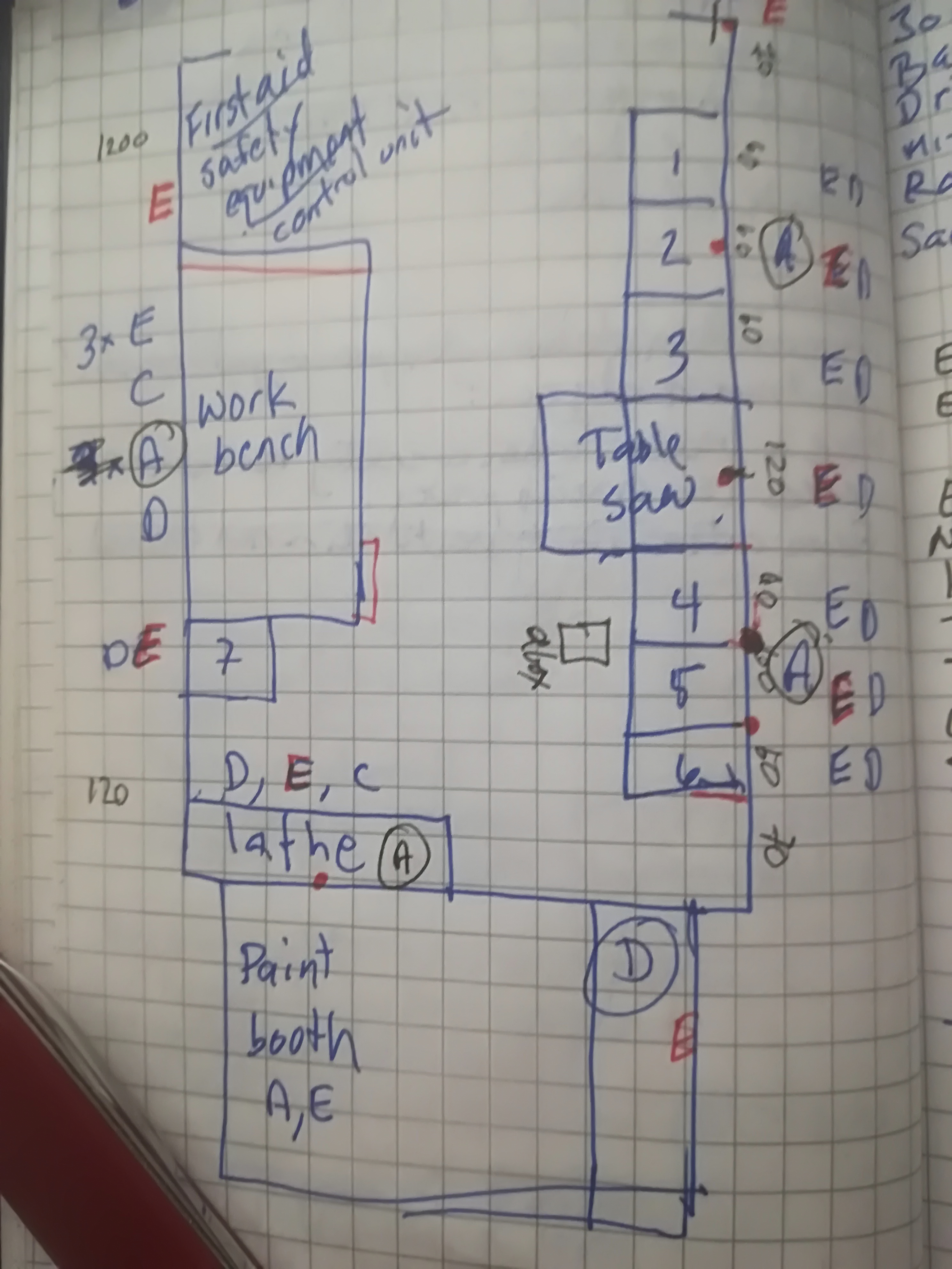
Equipment placement in version 1.1 and 1.2 (in parenthesis where it differs from 1.1): 1 = band saw; 2 = router table; 3 = cross-cut saw, previously referred to as a mitre saw; 4 = planer (drill stand); 5 = jointer; 6 = drill stand (planer); 7 = sander.
With version 1.2 the jointer was removed from the workshop, because it was decided that its work (edge planing) could be performed with a router table, provided that router table was made or purchased with separately adjustable split fences. The main reason why both the joiner and the planer were initially placed in the back half of the workshop was because that made them closer to the dust extractor. With rip saw in-feed at the back of the workshop, the rip saw fence would have been positioned along the wall of machine alley.
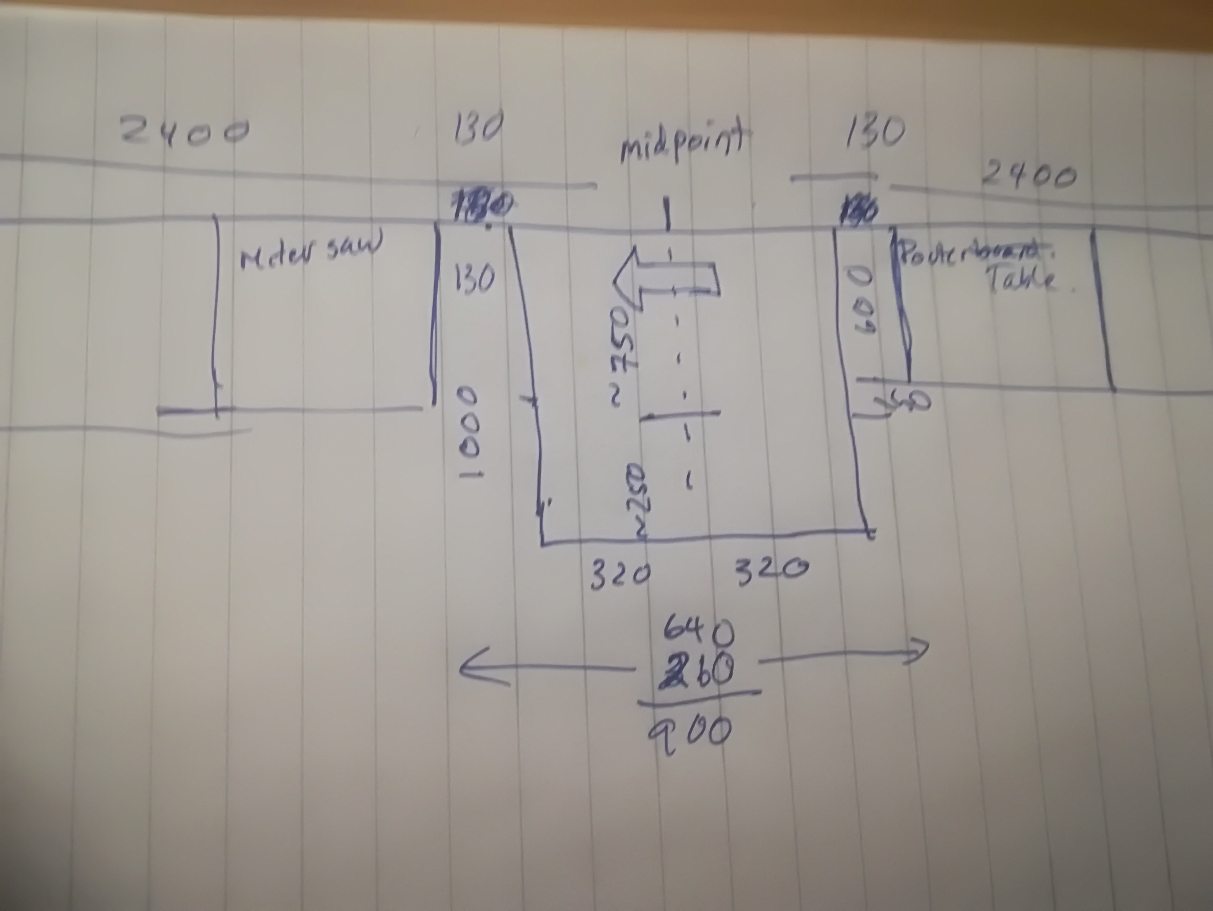
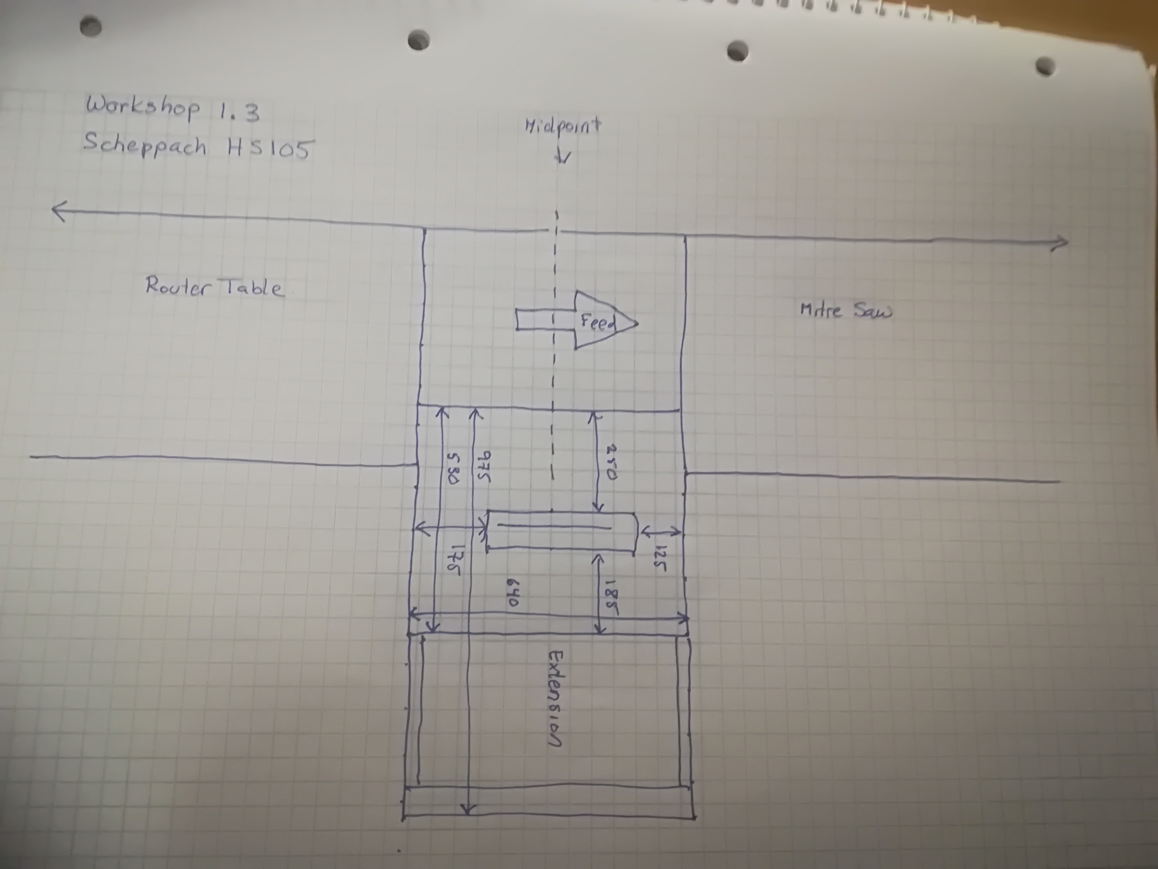
Currently, workshop design 1.3 is used for operational decisions. This changes the direction of feed, and changes the position of the rip saw fence to the middle of the workshop. In-feed is improved when the router table, aka shaper or spindle molder is co-located with the in-feed, and more poorly served when a cross-cut saw (aka chop saw, or sliding compound mitre saw) is on the in-feed side. Working sheet materials around a cross-cut saw is much more difficult than having to deal with a router table.
Machine Alley now has the band saw moved adjacent to the entry doors, then comes about 1150 mm of space that can be used for hand tools, portable electric tools and air tools. This is followed by the router table, rip saw and cross-cut saw, previously discussed. Another 1480 long space follows, part of the out-feed area that can be used for sub-component and smaller project assembly. At a future date, this area can be re-purposed to serve as a location for a wood lathe, removing it from its previous proposed location along the back wall. The drill press is located at the far end of the wall.
The planer, previously given a permanent position, is now regarded as a machine that only requires temporary placement.
Conclusions
While I would have liked to have had the dust extraction system, air lines and even workbenches to be in place, I am very happy that the three first iterations were not implemented. Procrastination has its benefits. The failure to implement the initial design has saved me from having to rip out components and start over, or to accept an inferior design.
All cutting machines, stationary as well as portable, are now all placed on Machine Alley. This simplifies dust extraction.