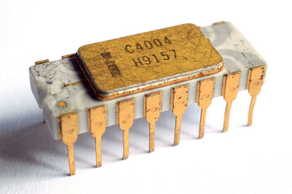
An Intel C4004 microprocessor with gray traces. (Photo: Thomas Nguyen)
Today (2021-11-15) is the 50th anniversary of the Intel 4004 microprocessor. This featured a 4-bit central processing unit (CPU). It was the first microprocessor to be sold as an electronic component. At the time of its development, Intel considered itself a memory chip manufacturer. At about the same time, three other CPU designs were being developed, but for specific projects. These were: Four-Phase Systems AL1, (1969); American Microsystems MP944 (1970); and Texas Instruments TMS-0100 (1971).
The Intel 4004 project began in 1969, when Japanese adding machine manufacturer Busicom, approached Intel to manufacture a chip it had designed. Intel was a start-up, so small that they didn’t have the staff to design the logic required. Thus, they came with a counter proposal, to build a general purpose computer-on-a-chip and to emulate the calculator architecture using a read-only memory (ROM) byte-code interpreter.
Frederico Faggin (1941 – ) was assigned responsibility for the project. He was able to design a customer-programmable microprocessor. The work included logic design, circuit design, chip layout, tester design and test program development. His initials F.F. were incorporated into the chip design. Assisting in the development process was Masotoshi Shima (1943 – ), a Busicom software and logic designer, but without any chip design experience. The chip was first used in the Busicom 141-PF adding machine.
Faggin is known for several microprocessor inventions. These include the buried contact, and the bootstrap load. He also created the basic methodology for random logic design using silicon gate technology. He was particularly vocal inside Intel in advocating the 4004 as a general purpose microprocessor, with a huge market potential. He subsequently led the design of the 4040, 8008 and 8080 processors.
Faggin was presented with the engineering prototype of their calculator with the first 4004. This was subsequently donated to the Computer History Museum.
Faggin and Ralph Ungermann (1942 – 2015) left Intel in 1974 to start Zilog. Intel’s reaction was to disown Faggin, and to rewrite company history. In particular, it credited more loyal, but less competent, employees, with the 4004 design.
Be thankful that today’s microcontroller is not your grandmother’s microcontroller.
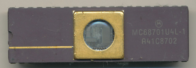
In the early to mid 1980s, one could use any microcontroller one wanted, as long as it was a Motorola 6800 EPROM (Erasable Programmable Read Only Memory). Thinking about those experiences almost 35 years ago is painful. Sensors required their own army of hardware connections for analogue to digital conversion. Relays were needed to connect any form of actuator, even a light bulb. Devices were programmed in Assembler. Any and every mistake required the removal of the microcontroller’s top so UV light could flood the chip to erase code. Each erasure took about 15 minutes. It also required everyone to use UV glasses during this process to prevent eye damage.
A Motorola EPROM Microcontroller from 1987. Designed to be erased using UV-light. (image: www.cpushack.com)
The situation didn’t change until 1993, when Microchip Technology introduced the PIC 16C84 EEPROM. Those two Es stand for electrically erasable. EEPROMs don’t need UV light to be erased, which meant that code could be changed instantaneously. The other main difference was the chip’s architecture. Most computers, use von Neumann architecture, storing programs and working data in the same memory. PIC controllers used Harvard architecture, which separated programs from working-data, which allowed programs to be stored in cheap read-only memory. This resulted in a massive decrease in price, and a massive increase in the number of processes that could use microcontrollers.
About the same time, in Trondheim, Norway, Alf-Egil Bogen and Vegard Wollan developed a RISC (reduced instruction set computer) processor, hence AVR, that also featured Harvard architecture. This concept was sold to the Atmel corporation, who began producing AVR microcontrollers, such as the ATmega8.
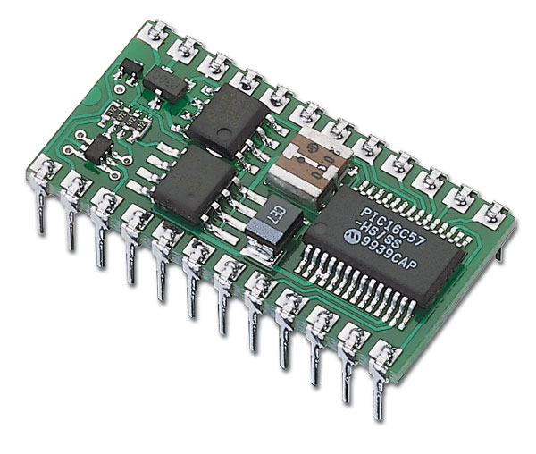
The main challenge of using a microcontroller, was that the user was expected to know what they were doing. Even getting the software to program a microcontroller could cost almost USD 1 000. Microcontrollers at this point were not for amateur hackers. Parallax, Inc.defused this issue by launching the BASIC Stamp, a microcontroller with its own BASIC interpreter. It was especially popular with electronics hobbyists. With this the programmer was essentially free, but only worked with the BASIC Stamp. In addition, BASIC Stamp microcontrollers were expensive.
BASIC Stamp, a user-friendly but expensive microcontroller. (Image: Parallax)
Wiring, an open-source electronics prototyping platform composed of a programming language, an integrated development environment (IDE), was developed by Hernando Barragán, starting in 2003. It was built on Processing, which offered a similar environment for multimedia, initiated by Casey Reas and Benjamin Fry. Although the Wiring IDE is written in Java, it comes with a C/C++ library that makes common input/output operations much easier. Wiring programs are written in C/C++.
At the Interaction Design Institute Ivrea in Ivrea, Italy, students initially used the BASIC stamp, but these units were expensive for students to buy. The Arduino project was started in 2003. It was a fork of Wiring that supported an ATmega8 microcontroller. The initial Arduino team consisted of Massimo Banzi, David Cuartielles, Tom Igoe, Gianluca Martino and David Mellis. but Barragán was not invited to participate.
Like the BASIC Stamp, the Arduino allowed any idiot capable of plugging in a printer cable and pressing download, to get a microprocessor to run. The printer cable was not only a power supply, it was also a mechanism for uploading code to the microcontroller.
The main difference between the BASIC Stamp and the Arduino board was that the Arduino was designed not only to give users simplicity, but to give the board longevity. The circuit had protective devices to prevent damage. My teaching experience shows that this is not foolproof, but a major help. Pin 13 includes its own LED, allowing the famous Blink program to run visibly, even without a LED fitted to the pin. It was a superior product.
Arduino has gone through some dark times. While in early 2008, the five co-founders of the Arduino project created a company, Arduino LLC, transferring ownership of the Arduino brand to the company. Boards continued to be manufactured and sold by external companies, with Arduino LLC receiving a royalty. This is a problematic situation for a company claiming to be open source. At the end of 2008, Gianluca Martino’s company, Smart Projects, registered the Arduino trademark in Italy (and thus the EU). When Arduino LLC tried to register the trademark in other areas of the world they discovered that it was already registered in Italy. Negotiations with Gianluca failed to bring the trademark under control of Arduino LLC. In 2014, Smart Projects began refusing to pay royalties. Its new CEO, Federico Musto, renamed the company Arduino SRL and created the website arduino.org.
By 2008, innovation had stopped at Arduino with the introduction of the Duemilanove board. Since then, there have been many different boards using various processors and the IDE code has been tweaked. However, there have been no revolutionary improvements. The Uno is an enhanced Duemilanove, and has been Arduino’s main board since September 2010.
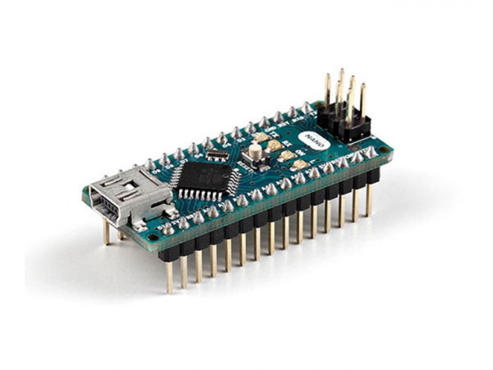
One of the challenges with working with an Arduino come from the design of its pins. These pins are located on the top of the board, using female 0.1-inch (2.54 mm) headers. While plug-in application shields are available that use male pins that fit into the female headers, this arrangement does not support effective use of breadboards. With the development of the Arduino Nano, male header pins on the underside of the board allow it to plug into breadboards. It lacks a DC power jack, and uses a Mini-B USB cable. This minimal board measures 43.18 mm x 18.54 mm.
The Arduino Nano predates the Uno, but has never achieved popularity among Arduino enthusiasts. (photo: Arduino.cc)
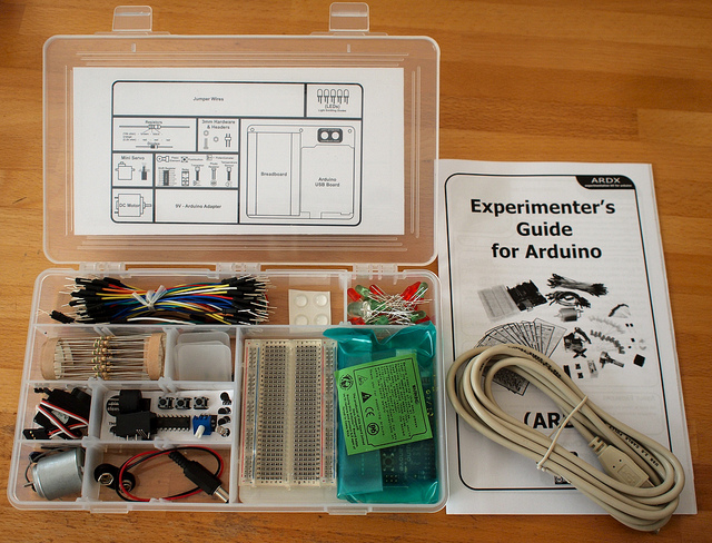
Perhaps the reason for the popularity of the Duemilanova and the Uno (and the relative failure of the Nano) was their use of the first two in Arduino kits, that were often made and supplied by third parties. The first ten kits using Duemilanovas were purchased for Leksvik Upper Secondary School and came from Oomlout . ( http://www.oomlout.com ) who described themselves in the following way: “What We Are We like to describe ourselves as a plucky little design house. We focus on producing delightfully fun, open source products. Where We Are A scattered organization we are based in Vancouver, British Columbia (manufacturing). We have satellite offices in Leeds, Yorkshire (design), and Point Roberts, Washington (shipping). There is no sprawling corporate campus to offer tours around, yet. But if you are in any one of our neighborhoods, drop us a line and we’ll see if we can arrange something.”
An Arduino ARDX kit fra Oomlaut. The USB printer cable would not fit in the box, and was not provided as part of the kit. (photo: Oomlaut.com)
The kits came with a plexiglass plate that held the Arduino board, and a half-size breadboard in place. There was also a box with sufficient hardware to allow at least ten to fifteen projects to be made. These projects showed the versatility of the microcontrollers in general, and the Arduino in particular, in many divergent areas. It was a winning formula.
MKR boards have their own form factor 61.5 mm x 25 mm, while claiming to use the minimal format found on the Arduino Nano. This means that the boards can be fitted directly onto a breadboard. The main difference is that the MKR boards use 3.3 Volts, and they will fry if supplied with 5 Volts. With low power consumption, MKR boards are targeted as battery-powered IoT “edge” devices, to be programmed via the Arduino IDE software.
There are now five Arduino MKR boards, each made for to satisfy a particular connectivity issue: MKR ZERO, MKR1000, MKR FOX 1200, MKR WAN 1300 and MKR GSM 1400. The person responsible for the MKR boards obviously has a defective keyboard, since the names use upper case letters exclusively.
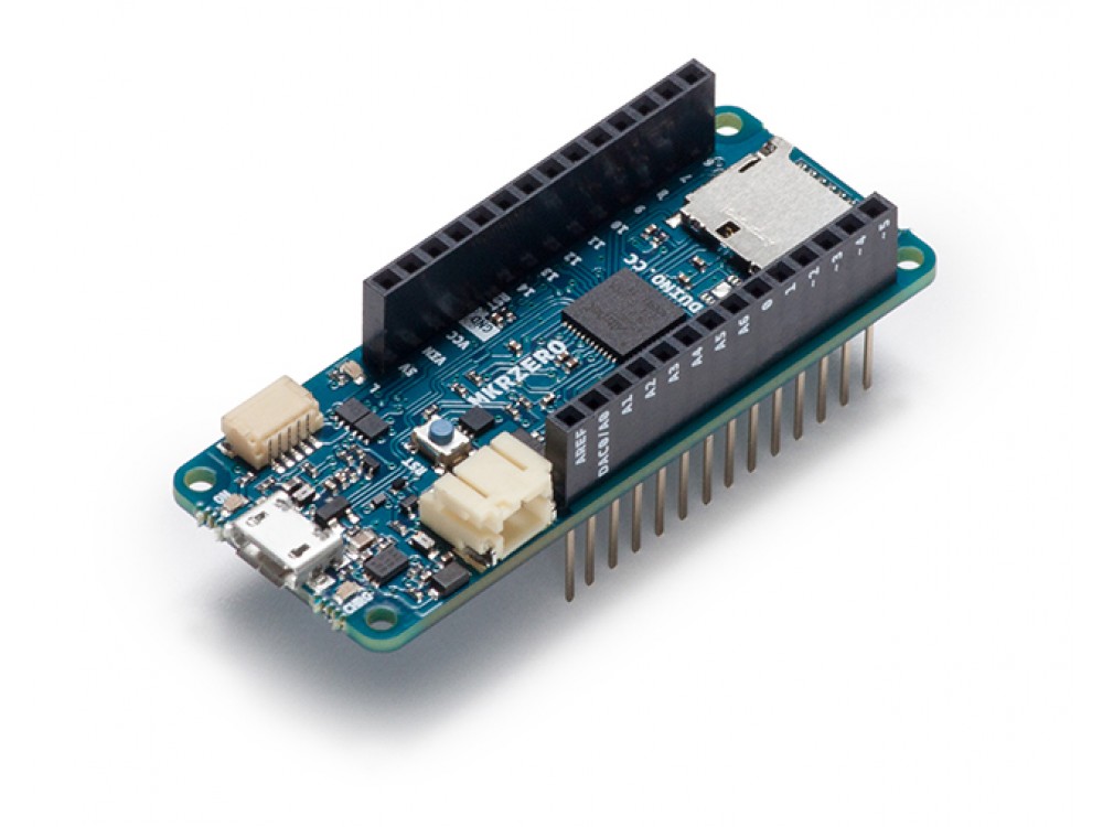
MKR ZERO distinguishes itself by having an on-board SD connector with a dedicated SPI interface (SPI1) that supports music files. Two libraries also support music applications: The Arduino Sound library can be used to play and analyze audio data, while the I2S library uses the I2S protocol to connect digital audio devices using the electrical serial bus interface.
An Arduino MKR ZERO designed for musicians and audiofiles. (photo: Arduino.cc)
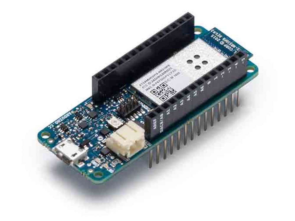
Arduino MKR 1000 is similar to the MKR ZERO adding conventional Wi-Fi connectivity but lacking an on-board SD and SPI interfaces.
Arduino MKR 1000, designed for IoT wifi connectivity (photo: Arduino.cc)
A LPWAN (low-power wide-area network) allows long range, low bit rate communicationbetween battery-driven sensors and other connected objects. LPWAN contrasts with a wireless WAN designed to connect users carrying large amounts of data. The primary advantage of a LPWAN is that it allows the deployment of sensors without investment in gateway technology.
The MKR family has two different LPWAN boards.
Arduino MKR FOX 1200 provides SigFox connectivity, and includes a two year subscription to the SigFox network. Sigfox uses proprietary technology for communication on the ISM (Industrial, Scientific and Medical) radio band, with a low energy, wide-reaching UNB (Ultra Narrow Band) signal that passes freely through solid objects. Sigfox is a network operator, so users have to wait for them to deploy, and then pay a subscription fee for each device (about 1€ per year).
Arduino MKR FOX 1200 designed for connectivity to SigFox’s proprietary network. (photo: arduino.cc)
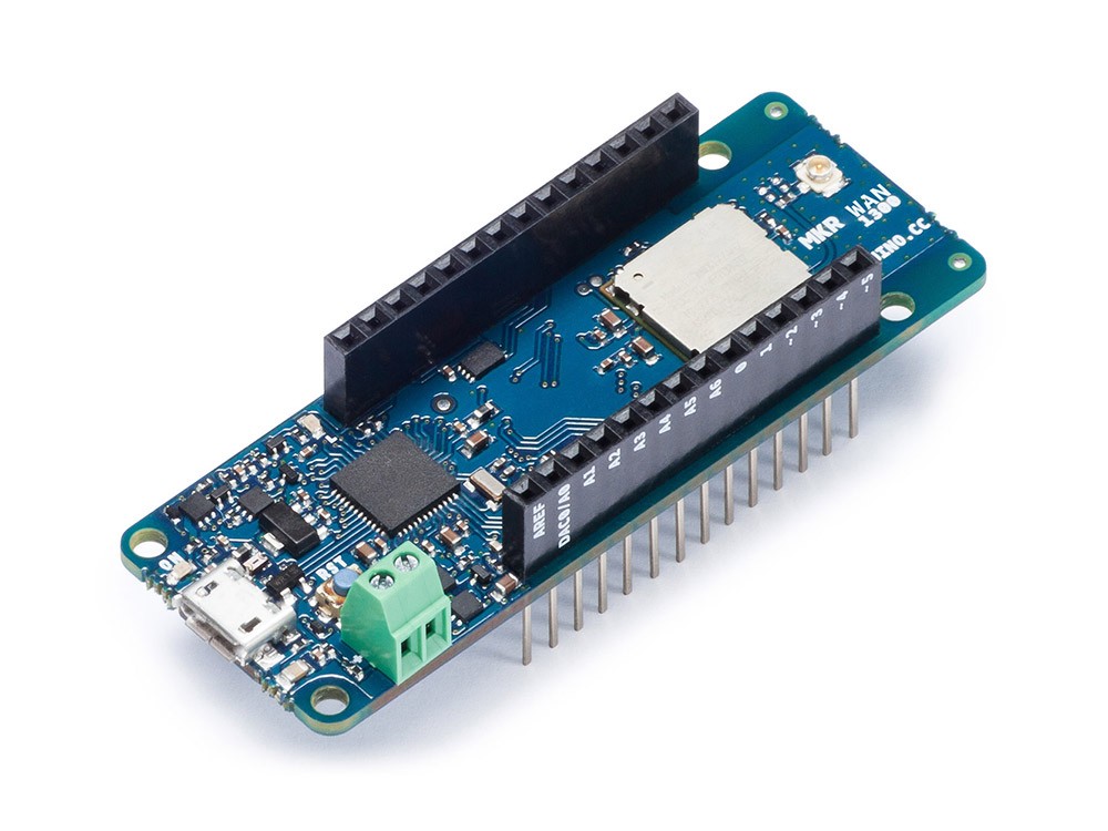
Arduino MKR WAN 1300 also provides LoRa connectivity, but by using a Murata Lo-Ra module. This uses the CSS (Chirp spread spectrum). With this form of LoRa, anyone can deploy a network to just cover a local area. It can be done at any time, and there is no subscription fee.
Arduino MKR WAN 1300 for open source connectivity. (photo: arduino.cc)
Arduino MKR GSM 1400 provides global 3G communications. It does not come equipped with a SIM card.
Arduino MKR GSM 1400 for connectivity through a GSM G3 network (photo: arduino.cc)
This weblog post was updated 2021/12/21. to eliminate Seeds from the title. This post formed part of a Needs, Seeds and Weeds website that belonged to my daughter, Shelagh. In addition, other things are also out of date, or my opinions have changed. Apart from the title, updating the text to a block format and other minor formatting changes, the text above this paragraph remains as it was before. Any significant content changes are found below this paragraph
I have totally given up on Arduino as a suitable microprocessor for any projects that I work on. Currently, I am using Raspberry Pi Picos, but would also consider using Teensy microprocesssors for audio projects. For more complex projects, Raspberry Pi currently offers even more powerful boards, including compute modules.
Rather than sticking with Raspberry Pi, the innovators at Cliff Cottage are using Asus Tinker Boards. The Tinker Board is simply a better machine. Not perfect, perhaps not even good, but better. A similar sea change may be happening with the Arduino.
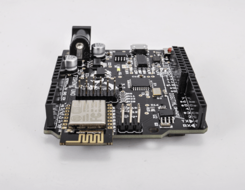
The Fishino Uno is yet another Arduino Uno board, in term of connectivity and size. However, it is more than that. It has many features that the Arduino lacks: internet connectivity, large storage capacity using a micro-SD card and an on-board RTC (real-time clock) with battery backup. There is a minimal change to the Arduino form factor, caused by a 7mm wifi antenna overhang.
The Fishino – more than another pretty face in the sea of microprocessors. (Photo: www.open-electronics.org)
These improvements make Fishino better suited for home automation systems, than the original Arduino. The WiFi module allows the Fishino to be used as a WiFi station and/or access point, and allows smartphone control even without a WiFi connection.
In summary, some of the characteristics of the Fishino that make it better than the Arduino.
Fully compatible with Arduino Uno
WiFi module on board, that can be uses in station mode, access point mode or both
MicroSD slot on board
RTC (Real Time Clock) with backup lithium battery on board
Increased current capacity on 3.3V supply section
Connectors compatible with breadboards
Fishino is the same size as an Arduino except for the 7mm wifi antenna overhang. (Photo: www.open-electronics.org)
For further information see: https://www.open-electronics.org/fishino-arduino-become-wireless/
Shield
A shield is a printed circuit board that fits on top of the main Arduino (or Fishino) board, offering additional attributes to the system. Here we will mention two that can be used in home automation.
Fishino Octopus
PWM – For the next few minutes please don’t ask what PWM means. Pretend that it refers to Portland International Jetport, or Peter Wallace Myrick or anything else … Just accept that there is something called PWM, and that it can be important.
Some motors, including those on sewing machines, require variable speed. In the past, a rheostat was used to adjust the electrical current flowing through it. This wastes power because it uses the same amount of energy regardless of the motor speed. What isn’t used to power the motor is released as heat.
What was needed was an efficient power adjusting tool. PWM solved this problem. On an Arduino / Fishino Uno there are only six PWM outputs. Many times this is far too few.
The Octopus expansion shield allows 16 PWM outputs and 16 additional digital inputs or outputs. Up to 8 of these can overlap, allowing a system to manage 128 PWM outputs and 128 digital inputs or outputs.
A Fishino Octopus powering 16 servo motors. (Photo: www.open-electronics.org)
Fishino Colibri
Engineers do not always have the greatest understanding of how the natural world functions. Colibri means hummingbird, and surprisingly, it is not a fish. An octopus isn’t a fish either, but we won’t force the issue.
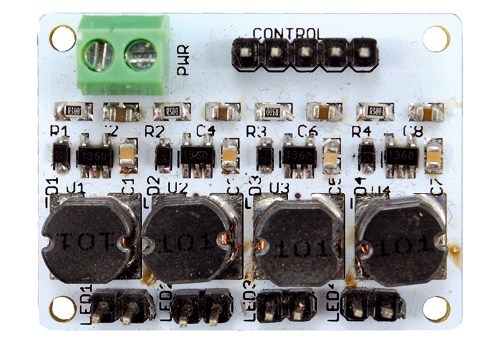
The Colibri is used to provide power to RGB LED lighting. These use 4 channels to provide a full range of colours using PWM control signals.
The Fishini Colibri – a RGB LED light controller. (Photo: www.open-electronics.org)
By the way, PWM stands for Pulse Width Modulation.