
In the last post, Ethan & Ethel had to do a lot of work, to keep track of their heating costs.
Time used = Time turned off – Time turned on. Example: 17h05m – 15h31m = 94m
They wrote down the time they turned on their heater, and then the time when they turned it off. They then subtract the “on” time from the “off” time to find the number of minutes the heater was on. This had to be repeated for every visit to the workshop with heat on. At the end of the month, they had to add all of these minutes together to find their monthly usage. What a boring job, and so unnecessary when a computer can do it, automatically! All that is needed is a few lines of code. Code that has already been written, and is waiting to be reused.
Workshop computer control means that computing equipment is running hardware and software that senses and activates workshop activities.
Stop the Press!
This post was originally written 2018-03-02. It is now 2018-08-11, more than five months later. Reviewing it at the time I was dissatisfied with the previous paragraph, that continued with, “a Raspberry Pi single-board computer will be used to run Home-Assistant software. The raspberry pi will be connected to two different Arduino micro-controllers using USB cables.”
The problem, both then and now, is that while the above solution would work, it is not optimal. Why should one use three components, when one should do? Ideally, a single microprocessor should be able to run 1) home automation software, in this case Home-Assistant; 2) connect to analogue sensors and have analogue input data converted to digital data; 3) connect digitally to relays to trigger activators; 4) communicate with other components on the local area network using wires (Ethernet); 5) receive electrical power over those same wires.
The best way forward to gain an understanding of workshop problems is to pretend that the ideal solution exists, a fantasy Unicorn IoT (Internet of Things) microcontroller.
Home-Assistant
If Ethan and/or Ethel are to work in a computer controlled workshop, one of the first things they need to control is the workshop computer. It should be designed in such a way that it can respond to their needs turning on and off lights, heat, tools, etc.
While a Raspberry Pi (and its clones and near relatives) is capable of running this software, an Arduino microcontroller is not.
Sensors
In a workshop there can be a large number of different sensors measuring all sorts of things. There can also be a large number of actuators using the same data. For example, both a heater and a vent may use data from a room temperature sensor, but in different ways. The heater may be activated if the work space is too cold. Once it gets hot enough it will shut off. If the temperature continues to rise, then a different actuator, the vent will be activated, but only if the outside temperature is lower than the inside temperature. To determine that, there needs to be a second temperature sensor, this one measuring the outside air.
A sensor is any device that measures a physical quantity. Temperature sensors can be found not only in the workshop space, but also inside machines. This Wikipedia article lists sensors by sensor type: https://en.wikipedia.org/wiki/List_of_sensors
Some of the other sensors in a workshop include: humidity, measuring water vapour in the air; infra red, detecting body heat; light, measuring light levels; smoke, detecting fires. Those are sensors that can be used anywhere in a house. There can be some sensors that are specific to a workshop: wood moisture content and dust particles in air.
Having so many sensors can be a major distraction, so from now on the focus will be on just one, a LM35 temperature sensor.
LM35 Temperature sensor
Several companies make temperature sensors, but Texas Instruments makes one that is world famous, the LM35. It costs about $1.50.
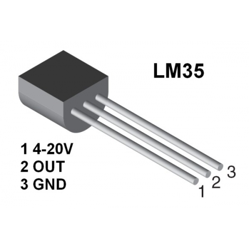
While information about the LM35 is available in a data sheet that contains more than enough information about every aspect of the sensor, most people don’t need to read it. Why? Because all of the engineering work has been done before. Since Ethan and Ethel will be using an Arduino, they just need to know how to connect a LM35 with an Arduino. Then they have to find a (free) program that uses the LM35, and upload it onto the Arduino. With a little practice, anyone can get a sensor working on an Arduino in about five minutes.
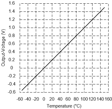
The LM35 is cool. The main reason is shown in this graph. Most sensors express themselves as a voltage that varies smoothly with the quantity being measured. On a graph this makes a straight line. The LM35 is exceptional, because at 0°C output voltage is 0V. Every 1°C up or down adds (with positive temperatures) or subtracts (with negative temperatures) precisely 10 mV. At 100°C, the output voltage is exactly 1V. The LM35 is also very flexible regarding input voltage. It can use anything from 4V to 20V.
ADC
Computers use digital data, and can’t normally read voltages directly. On micro-controllers there are Analog to Digital Converters (ADC) that automatically change an input voltage into a digital value. On the Arduino Uno, there are six analog pins that can read voltages from 0 V to 5 V (or 0 mV to 5 000 mV). This means that up to six different sensors can be connected to an Arduino board. There are ways to add more, if needed. Each sensor then has its voltage converted into a digital values between 0 and 1023. These analog pins have a sensitivity of 4.9 mV. So a voltage from 0 to 4.8 mV will be given a value of 0. From 4.9 mV to 9.8 mV they will be a value of 1. This will continue right up to 4 995.1 mV to 5.0 mV, where they will be given a value of 1023.
It takes about 100 µs (100 microseconds or 0.0001 s) to read an analog input. The maximum reading rate is 10 000 times a second. Usually, reading a temperature once a second is good enough. In fact, in some circumstances reading it every five minutes or every hour would make better sense, especially if all this data has to be stored.
Arduinos have ADC units, Raspberry Pis do not.
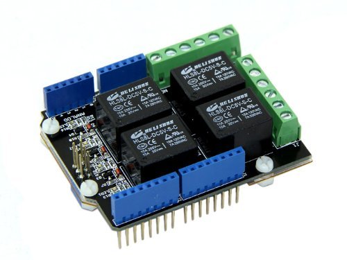
Relays
Microcontrollers do not respond well to large currents, and will be permanently damaged if connected to too many volts, amps or watts. If one wants to turn on an electric heater to warm up a space, this is typically done by a relay. A Relay is an electrically operated switch. When an electromagnet is activated with a low voltage, typically 5 V, it makes or breaks a high voltage circuit.
Many microcontrollers have supplementary boards that attach directly to pins on their main boards. Both the Raspberry Pi and the Arduino have them. On a Raspberry Pi they are called Hats (Hardware Attatched on Top). On the Arduino they are called shields. The Raspberry Pi hats allow the main board to identify a connected hat and automatically configure the pins.
Communication
For automation systems, wired communication is preferred. The most common form of wired communication is the Ethernet, developed at Xerox PARC (Palo Alto Research Center) in 1973-4 and used ever since. Most people would be advised to use CAT 6A cable, for workshop automation.
In the future, almost every significant power tool in a workshop will be connected to the local area network, including dust collection and air filtering equipment. Even in home workshops, various variants of CNC (computer numeric controlled) equipment will be taken into use, including 3D printers and laser cutters.
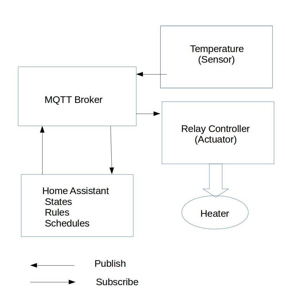
Microprocessors in the 1970 would process data in a single program that ran continuously. In the 21st century, not so much. The reason for this is that each sensor (and each actuator) is treated as a separate object. Sensors publish data, about a specific state, and actuators subscribe to the data they need to make decisions about how they will operate. To do this they use a publish-subscribe protocol called MQTT. It has been around sine 1999.
PoE (Power over Ethernet)
Power over Ethernet allows electrical power to be sent over the same Ethernet cable used to send and receive data to a device. This simplifies life considerably. There are no batteries to change or high-voltage power cables to install. The main challenge is that only a few microcontrollers are capable of utilizing this feature. Using a Hat or shield with PoE connectivity is another possibility.
The previous post refers to Ethan & Ethel 03: Electrical Power. It was published 2017-11-25.