Some people study structural engineering to work professionally designing structures. Others, such as myself, are content to remain amateurs, but want to understand how structures function. There are three principles:
- Efficiency = calculations of forces/stresses
- Economy = cost, but also seen in its social context
- Elegance = form/appearance based on engineering principles, not decoration
Two of my favourite online courses involved the art of structural engineering, offered by Princeton University, and presented by Maria Garlock. I completed the first, about bridges in 2016, and the second about vaults = long-span roofs, in 2019. A third, about towers, was announced along with the others in 2016, but has never emerged.
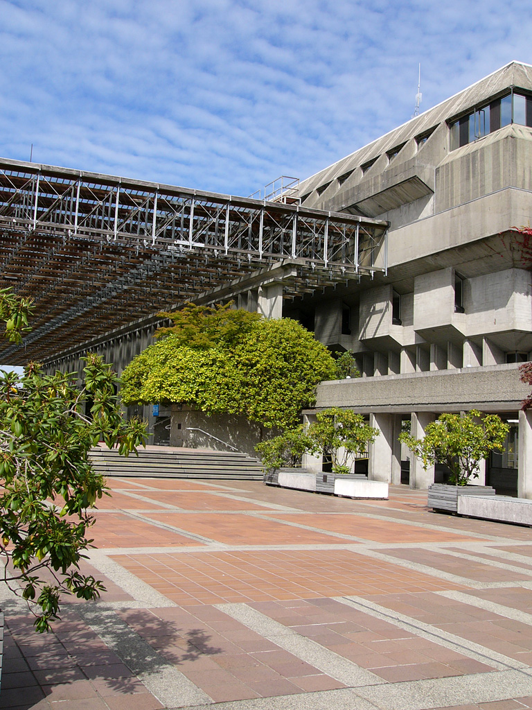
I believe the first time I ever seriously looked at the structure of a modern building, was in the mid 1960s. It was a cantilevered roof, outside the library at Simon Fraser University, It seemed to be a structure that was: endless, simple, appropriate and elegant, in contrast to the brutalism, surrounding it.
Cable-stayed Bridges

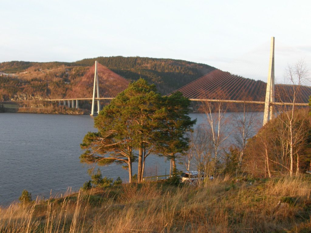
When we moved to Inderøy in 1988, preliminary work on Skarnsund bridge had already begun, although work on the bridge itself waited until we moved in. Thus, I had ample opportunity to observe the construction of what would be the cable-stayed bridge (CSB) with the longest main span = 530 m. The bridge was, 1 010 m long.
At about the same time, I was aware of two other CSBs, along the Fraser River in British Columbia. With a bridge length of 2 525 m with a main span length of 465 m, the Alex Fraser Bridge (named for Alex Fraser (1916 – 1989), a former British Columbia Minister of Transportation) was the longest cable-stayed bridge in the world when it opened 1986-09-26, and remained the longest in North America until the Arthur Ravenel Jr. Bridge in South Carolina with a total length of 4 000 m and a main span length of 471 m, opened in 2005.
The SkyBridge between New Westminster and Surrey, was built between 1987 and 1989, it carries trains of the Expo Line of TransLink‘s SkyTrain across the Fraser River. It was much smaller, with a total length of 616 m and a main span length of 340 m.
One of the most significant characteristics to consider when evaluating structures is completion time. CSBs do not require the same levels of anchoring found in alternative designs, such as suspension bridges. A CSB can handle greater forces, allowing the deck to have more resilience against wear and tear because of its greater rigidity. In areas subject to earthquakes, CSBs are noted for their ability to better withstands shaking compared to most other bridge types. They also resist cross-winds better, and maintain its shape better while supporting the heavy loads.
CSBs use less about 30% less labour than other comparable designs. This advantage is one of the main reasons why CSBs are becoming so popular. Spans of different lengths acn be connected together with support pillars or towers to create a bridge of almost any length. The Jiaxing-Shaoxing Sea Bridge is the world’s longest and widest multi-pylon cable-stayed bridge. It is 10.14 km long, and 50 m (8 lanes) wide. Construction started in 2008, and was completed in 2013.
A CSB can be built using many different technologies. The side-spar design is the most common, as it only needs one tower and supports that are on just one side of the structure. In other places a cantilever-spar design is more appropriate. This provides a single spar that is located on one side of the bridge. Other options allow for cradle systems or multiple towers.
Cables provide the structure with the temporary and permanent supports it requires simultaneously. More cables are added as the bridge grows in length (and mass). Cables help to displace forces throughout the structure to prevent one section from receiving excessive stress. After the bridge opens, these cables will stabilize the structure as it distributes any unexpected forces.
Cable symmetry provides more stability and strength. When the spans on either side of the pillar/ tower are of the same length, then the horizontal forces help to balance out the effects of each other. That means there is less need for large ground anchors to support traffic as it passes along the deck.
There are four different types of cable rigging for CSBs less than 3 km in length. Mono design uses a single cable from its towers to provide support. This is rare unless the span being crossed is relatively small.
Parallel/ harp design, uses cables approximately parallel to each other so that the height of their attachment is proportion to their distance from the tower and their deck mounting.
Fan design requires cables to connect to or pass over the top of the towers. This option is preferred when cable access is necessary. to the cables while maximum supports are needed to create a stable deck environmental requirements too.
Star design spaces the cables apart on the tower, but connecting them to a single point or closely-spaced points on the deck instead of spreading them across the span.
Single arrangement refers to the use of a single column for cable support. This column is usually placed midway across the deck, but it can be placed along one of the sides. Double arrangement uses pairs of columns on both sides of the deck. Portal arrangement adds a third member that connects the tops of the two columns. This provides additional strength for traverse loads. A-shaped arrangement achieves the same goal as the portal design by angling the two columns toward each other, so that they meet. Columns can be vertical, curved or angled relative to the bridge deck.
CSBs are not perfect and do not provide a universal bridge solution. Here are some imperfections/ limitations.
Computer-aided design for cable-stayed bridges has increased the maximum span, but this still has limits. Most CSBs will have a span between 100 and 1 100 m. They are often preferred for pedestrian bridges and situations with unusual loading configurations might be present. Currently, the longest single span is found on the Russky Bridge, in Vladivostok Russia, with a length of 1 104 m.
While CSBs can provide a consistently supportive deck when there are crosswinds present over a span, they do not work well with constantly high wind speeds, which will encourage the deck to rock, which over time will loosen the support cables, which could lead to structural failure = a bridge collapse. This occurred with a cable-stayed bridge at Genoa, Italy, 2018-08-14. The bridge was built in 1967 largely of concrete. The collapse killed 43 people.
CSB design typically places the support structure bundle areas in places where a physical inspection becomes challenging. Add in the reduction of anchors, and the routine maintenance becomes intensive (read: expensive). Although the initial installation cost might save 30% of labour costs, maintenance costs will eventually eliminate those savings, over a design lifespan that is now typically 100 years.
Most 21st century CSBs are constructed out of concrete and steel to create a rigid structure. These materials need protective coatings to ensure integrity and prevent corrosion and metal fatigue. At Skarnsund, seven coatings were applied to the cables, when the bridge was built, to protect them against corrosion. This is common practice, especially in coastal regions, due to salt in the air.
Cable-stayed bridges date back to 1595, where designs were found in Machinae Novae, a book by Croatian–Venetian inventor Fausto Veranzio. The cable-stayed bridge design fell out of favor in the early 20th century because it simply lacked the strength to support traffc, although it was still used for short-to-medium spans, suspension bridges grew in popularity. They offered increased durability despite higher installation costs.
When the populations of the planet began to recover then increase after World War II, CSBs became more popular: They could be built quickly and cheaply, and were a cost effective way to improve transportation infrastructure. In addition, these bridges were aesthetically pleasing, strong and durable.
Geodesic domes
The first geodesic dome was designed by Walther Bauersfeld (1879 – 1959) for a planetarium for Zeiss, in Jena, Germany, located on a building roof. Construction was started in 1912 and completed in 1923. This structure is considered the first geodesic dome, which is a polyhedron = a three-dimensional shape with flat polygonal faces, straight edges and sharp corners or vertices. More specifically, this particular building was an icosahedron = a polyhedron with 20 faces. A convex regular icosahedron = a regular icosahedron, is one of the five regular Platonic solids, and is represented by its Schläfli symbol, containing 20 triangular faces, with 5 faces meeting around each vertex.
Some 26 years later, Richard Buckminster Fuller (1895 – 1983) reinvented and popularized this design.

Photo: Differense, 2012-01-11.
Lloyd Kahn (1935 – ), who wrote Domebook 1 (1970) and Domebook 2 (1971) became disillusioned with geodesic domes, because they were smart but not wise. Disadvantages include: sheeted building materials such as plywood come in rectangular shapes that are wasteful to cut into triangles, increasing construction costs; fire escapes are problematic; windows are problematic, and expensive; electrical wiring installation requires increased labor time; expansion and partitioning are difficult; domes are difficult/ impossible to build with natural materials.
Others comment: air stratification and moisture distribution within a dome are unusual, resulting in degrade wooden frames and interior paneling; privacy is difficult because partitioning is difficult; sounds, odors and reflected light tend are diffused through the entire structure; wall areas can be difficult to use; some peripheral floor areas lack of headroom; circular plan shapes are difficult to use; rurnishers and fitters design with flat surfaces in mind.
Some dome builders, especially in the 1960s and 1970s, found it hard to weather-seal domes because of their many seams.
The most effective waterproofing method with a wooden dome is to shingle the dome. Peaked caps at the top of the dome, or to modify the dome shapes are used where slope is insufficient for ice barrier. One-piece reinforced concrete or plastic domes are also in use, and some domes have been constructed from plastic or waxed cardboard triangles that are overlapped in such a way as to shed water.
Notes: This weblog post was inspired by Incredible Crossing: The History and Art of the Bridges, Tunnels and Inland Ferries that Connect British Columbia (2022), written by Derek Hayes (1947 – ). We also have and regularly refer to his historical atlases of: Vancouver and the Lower Fraser Valley (2006); California (2007); North American Railways (2010); Washington and Oregon (2011); British Columbia (2012); Early Railways (2017); Iron Road West [British Columbia railroads] (2018). His latest book is: Quest for Speed: The definitive history of high-speed trains (2024).

