Optics 8

This is a Celestron Nexstar 8SE, often described as a good telescope for beginners/ hobbyists. It is the biggest telescope in Celestron’s iconic orange tube family. Its optics are acceptable, and it gathers lots of light. It is even affordable, at about US$ 1 000. Despite this, I am unconvinced this is a telescope for me. There is too much automation, hiding its operations. I want to know what is happening. Photo: Celestron.

This weblog post is the eighth of a series about optics and optical equipment. Optics 8 is about astronomical telescopes. Optics 9 is about microscopes. Later in 2025, two additional posts will appear: #10 is about digital cameras; #11 is about digital photograph collections.

Scandinavian winters are long and dark. Every year, in January, I go through a period where I considered acquiring a telescope. So far, I have not done so. In large part, it has to do with the reality of cloud cover. Norway is one of the most extreme places in the world for cloud cover. That said, Trøndelag is better than most places in Norway.

There has only been one type of telescope I have ever consider buying: a Celestron 8.

Before discussing it, and other telescopes suitable for amateurs, there is the history of astronomy to endure.

Johannes Kepler (1571–1630) investigated some of the laws of optics in his lunar essay (1600). In 1603, Kepler focused on optical theory, published as Astronomiae Pars Optica = The Optical Part of Astronomy (1604). It described the inverse-square law governing the intensity of light, reflection by flat and curved mirrors, principles of pinhole cameras, the astronomical implications of optics such as parallax and the apparent sizes of heavenly bodies. This work provides a foundation for modern optics, despite the absence of anything about refraction.

In physics, refraction is the change in direction of a wave passing from one medium to another or from a gradual change in the medium. Refraction of light is the most commonly observed phenomenon, but other waves such as sound waves and water waves also experience refraction.

Willebrord Snellius (1580–1626) developed the mathematical law of refraction = Snell’s law, in 1621. René Descartes (1596–1650) used geometric construction and the law of refraction = Descartes’ law, to show that the angular radius of a rainbow is 42°. He developed the law of reflection, Dioptrique (1637, French) = Optics = Dioptrics (both English) a short treatise that was the first published to mention this law.

Christiaan Huygens (1629–1695) wrote several works about optics. These included Opera reliqua and Traité de la Lumière (1690) which presents a wave theory of light. This theory was initially rejected in favour of Newton’s corpuscular theory of light, until Augustin-Jean Fresnel (1788 – 1827) adapted Huygens’s principle to give a complete explanation of the rectilinear propagation and diffraction effects of light in 1821. This principle is now known as the Huygens–Fresnel principle.

Isaac Newton (1643–1727) investigated the refraction of light, demonstrating that a prism could decompose white light into a spectrum of colours, and that a lens and a second prism could recompose the multicoloured spectrum into white light. He also showed that the coloured light does not change its properties by separating out a coloured beam and shining it on various objects. Newton noted that regardless of whether it was reflected or scattered or transmitted, it stayed the same colour. Thus, he observed that colour is the result of objects interacting with already-coloured light rather than objects generating the colour themselves. This is known as Newton’s theory of colour. From this work he concluded that any refracting telescope would suffer from the dispersion of light into colours, and invented a reflecting telescope (today known as a Newtonian telescope) to bypass that problem. By grinding his own mirrors, using Newton’s rings to judge the quality of the optics for his telescopes, he was able to produce a superior instrument to the refracting telescope, due primarily to the wider diameter of the mirror.

In 1671 the Royal Society asked for a demonstration of his reflecting telescope. Their interest encouraged him to publish his notes On Colour, which he later expanded into Opticks. Newton argued that light is composed of particles or corpuscles and were refracted by accelerating toward the denser medium, but he had to associate them with waves to explain the diffraction of light (Opticks Bk. II, Props. XII-L). Later physicists instead favoured a purely wavelike explanation of light to account for diffraction. Today’s quantum mechanics, photons and the idea of wave-particle duality bear only a minor resemblance to Newton’s understanding of light.

In his Hypothesis of Light (1675), Newton posited the existence of the ether to transmit forces between particles. In 1704, Newton published Opticks, in which he expounded his corpuscular theory of light. He considered light to be made up of extremely subtle corpuscles, that ordinary matter was made of grosser corpuscles and speculated that through a kind of alchemical transmutation “Are not gross Bodies and Light convertible into one another, …and may not Bodies receive much of their Activity from the Particles of Light which enter their Composition?”

A Telescope

Selecting the right equipment is vital in amateur astronomy. Optical quality is the most important characteristic of any telescope because it contributes significantly to the clarity of celestial bodies.

The three most commonly used types of telescopes:

1. Refractors: These use glass lenses at the front of the tube, a design often favoured for planetary observations.

2. Reflectors: These use mirrors instead of lenses. These are preferred for observing deep sky objects such as faint galaxies and nebulae.

3. Compound/ catadioptric: These combine lenses and mirrors. They are versatile, and can be used for viewing a variety of celestial objects.

The Tracking Platform

A telescope tracking platform can be built to allow a telescope to move in sync with the rotation of the Earth: to track stars, planets and other celestial objects as they move across the sky. While mechanical components provided timing, increasingly computers provide this today. Part of my interest in tracking involves the Forth programming language.

Everything in the night sky is in constant motion. This is mainly due to Earth’s rotation. Without a tracking system, a telescope, regardless of its quality, will only provide fleeting views. Tracking systems help a telescope to consistently follow celestial bodies, by moving the telescope at a similar rate and direction, mimicking the sky’s movement. This is especially important for astrophotography, that could require long exposure times.

Building a telescope tracking platform requires diligence, patience and persistence. Platforms can be complex and require fine-tuning and troubleshooting. Telescope tracking platforms come in two basic types:

Alt-Az Mounts: They move up-and-down (altitude) and side-to-side (azimuth). These mounts are often easy to use, making them suitable for beginners, for general observation and short-term tracking. They are not suitable for long-term tracking or astrophotography.

Equatorial Mounts: These mounts rotate along an axis parallel to Earth’s rotation. They require alignment with the Polaris = North Star. Equatorial mounts offer superior tracking for longer periods and are needed for astrophotography.

A mount alone doesn’t make a perfect tracking system. Location, local climate, the telescope’s size and weight have to be taken into consideration, along with motor drives and functionality.

Designing a telescope tracking platform is dependent on location. This impacts the effectiveness of a tracking system. A northern hemisphere, polar alignment will be different from that in the southern hemisphere. The altitude and azimuth of the celestial pole vary with latitude and longitude.

Humidity and temperature influence the telescope’s operation. In extreme cold, the lubricants in the mounts may thicken, hampering smooth movements. High humidity can lead to rusting of the metal parts.

The size and weight of a telescope also affect mount choices. Heavier telescopes require sturdier mounts to support their weight.

Maximum weight capacity varies with the mount. A typical amateur alt-azimuth mount can have a mass of 20 kg, while for an equatorial mount this can be 50 kg. While a a casual stargazer, can co-exist with an alt-azimuth mount for general observation, someone actively engaged in astrophotography, will need an equatorial mount, because of its superior tracking capabilities.

While tracking mount components are widely available online, it is sensible to acquire all the necessary materials before starting to build a telescope tracking platform. This prevents surprises and unnecessary delays. The functionality of the platform directly depends on component quality.

Some crucial components include the mount. Metal bars are needed for the base and rocker. Here, durability is important, so consider stainless steel or aluminum. Quality ball bearings used in the pivot point, will ensure smooth rotation of the platform. Motor and Gears should be selected to enable auto-tracking, with an adjustable motor speed capable of matching the Earth’s rotation.

Minimum tool requirements, include a screwdriver set, drill, hacksaw, wrenches and a level.

Before building the telescope tracking platform create a detailed design on paper or using design software. This design should show the mount, metal bars, ball bearings, motor and gears.

Start assembling the components beginning with the mount. Because it forms the core support system for the tracking platform, it must be sturdy and well-balanced. Affix the metal bars to provide a frame that can withstand your telescope’s weight, ensuring better stability and tracking accuracy. Place ball bearings in strategic locations to allow smooth rotation of the platform. Connect gears appropriately to the motor, to ensure their rotation is synchronized with the tracking process.

Integrate a controller into the platform to governs the motor speed and direction. Most modern controllers come with a capability to store star maps and tracking speed presets to make tracking easier and more efficient. Once the platform build is completed, a regular maintenance schedule must be devised, and followed.

Once the telescope tracking platform is assembled, it is crucial to run initial tests to ensure everything functions as expected. Drift alignment aligns the telescope with the Earth’s axis of rotation. Point the telescope at a bright star near the celestial equator and monitor its movement. If everything is correctly assembled and calibrated, the star should stay stationary in your telescope’s field of view. If the star drifts, adjustments will be necessary.

Correct controller calibration is essential to align the telescope with celestial objects. Polar alignment aligns the telescope’s rotational axis with the North Star.

Mechanical issues often involve simple corrections. Ensure the metal bars are firmly in place, the ball bearings move freely, and the gears are properly interlocked. Listen for unusual noises when it is operating. This could indicate a component is not operating as it should.

Power supply issues can cause problems. This applies to both battery and mains power. Ensure the supplied voltage matches the motor’s requirement, and there are no power fluctuations.

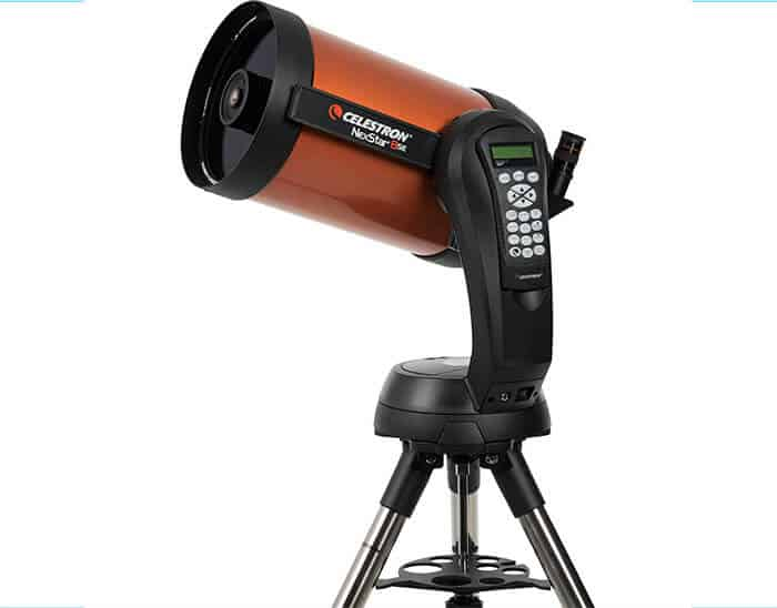
The Celestron Nexstar 8SE (shown in the photograph at the beginning of this post) is one often suggested for amateurs. It has a fully automated GoTo Mount, allowing users to select an object they want to observe with a database of 40 000 + objects. At the push of a button, the telescope will automatically point to it. The telescope is compact and Portable. With its Schmidt-Cassegrain optics it has a 20 cm aperture with good light-gathering power allowing views of the moon, other planets and deep-sky objects.

The telescope comes with a built-in wedge to polar align the telescope. A camera adaptor will allow the connection of a mirrorless or digital single lens reflect (DSLR) camera, for astrophotography. Other accessories are available that extend capabilities.

Tom Johnson (1923 – 2012) was an American electronics engineer and astronomer who founded Celestron, a company which revolutionized the amateur astronomy. He served as a military radar technician during World War II. In 1955, he started Valor Electronics, which produced electronics for military and industrial use, in Gardena, near Los Angeles, in California.

Celestron was created as the Astro-Optical division of Valor in 1960. Johnson had been looking for a telescope which could be used by his two sons, but found no child-friendly models on the market at the time. While building a 6-inch reflector telescope in 1960, Johnson encountered a lens-grinding kit. After several days of hand grinding, he invented a machine that would grind the lens for him.

Soon, the company was attempting to build various models of Schmidt–Cassegrain telescopes. However, these proved difficult to mass-produce because they needed Schmidt corrector plates, a hard to manufacture aspheric lens. To solve this production problem, company engineers invented a new type of telescope, the Celestron 8 in 1970, that was compact, affordable and easy to manufacture.

Meanwhile, further north in Watsonville, California, Meade Instruments, founded by John Diebel (1943 – ) in 1972, started selling Japanese telescopes. It became the world’s largest manufacturer of telescopes, starting in 1976. Unfortunately, they used litigation as a means of preventing competition. They ceased operation in 2024, after losing some important lawsuits.

The largest telescope brand in the world is now Sky-Watcher, established in 1999 by the Synta Technology Corporation of Taiwan. It markets telescopes and astronomy equipment, such as mounts and eyepieces, aimed at the amateur astronomy market. The products are manufactured in Suzhou, China. The brand is primarily distributed in North America and Europe.

Buying a telescope is usually an easy and inexpensive way of acquiring an astronomical telescope. However, some people are more inclined to make rather than to buy. Amateur telescope makers (ATMs) build telescopes as a hobby, for personal enjoyment of a technical challenge. They will claim, often to a spouse, that they are saving money, but this is seldom more than an excuse. Sometimes it is done to provide custom features on a telescope, or for research purposes.

John Lowry Dobson (1915 – 2014) was an American amateur astronomer, best known for the Dobsonian (light bucket) telescope, a portable, low-cost Newtonian reflector telescope. He promoted awareness of astronomy through public lectures and sidewalk astronomy performances. His Dobsonian telescope is an alt-azimuth mounted Newtonian telescope design popularized in 1965. It vastly increasing the size of telescopes available to amateur astronomers. Features included a simple, easy to manufacture, mechanical design, using easily available components to create a large, portable, low-cost telescope. The design is optimized for observing faint deep-sky objects such as nebulae and galaxies, with a large objective diameter, short focal length. Their portability allowed travel to less light-polluted locations.

At some future date, I intend to construct a small astronomical observatory, with its own telescope. The major problem with Vangshylla is its lack of clear skies. The Climate Research Unit of the University of East Anglia calculated cloud cover between 1991–2020 in 196 sovereign countries and Greenland. Norway had 81.5% cloud cover. Algeria has the least at 21.0%. There are only two countries with more cloud cover than Norway: São Tomé and Príncipe with 83.5%, while Greenland has 83.7%. Finland, the United Kingdom and Sweden are close with 79.6, 78.4 and 78,2%, respectively.

The following applies to Steinkjer, ca. 35 km north east of Vangshylla. In Steinkjer, the average percentage of the sky covered by clouds experiences significant seasonal variation over the course of the year. The clearer part of the year in Steinkjer begins around 04-07 and lasts for 5.3 months, ending around 09-17. The clearest month of the year is May, during which on average the sky is clear, mostly clear, or partly cloudy 45% of the time. The cloudier part of the year begins around 09-17 and lasts for 6.7 months, ending around 04-07. The cloudiest month of the year is January, during which on average the sky is overcast or mostly cloudy 74% of the time.

Of Canada’s sunniest places = least cloud cover, ranks 9 to 18 (with one exception #13) are cities in British Columbia. These are: # 9 = Kelowna (where my mother grew up), # 10 = Kamloops (where Trish’s sister and other relatives live), # 11 = Penticton, # 12 = Vernon, # 14 = Prince George, # 15 = Abbotsford, #16 = Nanaimo (where my father grew up), # 17 = Chilliwack and # 18 = Victoria.

In my childhood, I visited the The Dominion Astrophysical Observatory, located on Observatory Hill, in Saanich, British Columbia, near Victoria. It was close to the experimental farm, also in Saanich, where my uncle was director. The main instrument is a 1.83 m Plaskett telescope. In its day, the observatory was a world-renowned facility where many discoveries about the Milky Way were made. It was one of the world’s main astrophysical research centres until the 1960s.

The Plaskett telescope was planned to be the largest telescope in the world, but delays caused by World War I, and production errors requiring two regrindings of its mirror, meant it was completed 1918-05-06, six months after the 2.54 m Hooker telescope at Mount Wilson Observatory, in Los Angeles, California.

Note: This post was cloned as Optics 5 from Optics 4 on 2024-03-23. It was saved, for the first time at 8:00. On 2024-04-09 at 20:09 it was scheduled to be published 2024-06-22 at 12:00. On 2024-04-27 it was reconstituted as Optics 8 and rescheduled to be published 2025-01-18 at 12:00. Later that date was changed to 2025-01-25.

Optics 7

Originally, this photo was supposed to be one of Trish’s maternal grandmother’s opera glasses. Immediately before publication, they could not be found for a photo shoot. So this pair, appearing in Wikipedia were substituted. Early 20th century mother of pearl opera glasses & leather case. The glasses are marked with the name of the vendor “Ryrie Bros. Toronto” Photographer: Sobebunny, 2009-12-26.

This weblog post is the seventh of a series about optics and optical equipment. This post is about binoculars, but also includes opera glasses, monoculars and spotting scopes. Future posts: # 8 is about astronomical telescopes; and, #9 is about microscopes. Later in 2025, two additional posts will appear: #10 is about digital cameras; #11 is about digital photograph collections.

Binoculars specification values include information about strength (magnification power) and size (objective lens diameter). These are typically designated with two numbers, such as 8×40, where 8 is the magnification power while 40 is the diameter (in millimeters) of the objective lenses = the lenses closest to the object being viewed. Objective lens size tells: 1) how big physically the binoculars are, and 2) how much light they can gather. These numbers fail to provide information about the quality of the optics or other features such as: rubber protective covering, waterproofing and fog-proofing or – often importantly – type of prism and type of glass.

Binoculars provide users with a three-dimensional image because each eyepiece presents a slightly different image to each eye and this parallax = displacement = difference in the apparent position, allows a viewer’s visual cortex to generate an impression of depth. Monoculars are unable to achieve this.

Most early binoculars used Galilean optics = a convex objective and a concave eyepiece lens. It presented an erect image but with a narrow field of view and low magnification. This construction is still used in cheap models and opera glasses. Aprismatic binoculars with Keplerian optics = twin telescopes, provides each tube with relay lenses to erect the image. A relay lens is a lens or lens group that inverts an image and extends the optical tube. Relay lenses are found in refracting telescopes, endoscopes and periscopes to extend system length. This is done before the eyepieces, which is used to invert an image.

An endoscope = an inspection instrument composed of image sensor, optical lens, light source and mechanical device, which is used to look deep into the body by way of openings such as the mouth or anus. A periscope = an instrument for observation over, around or through an object, obstacle or condition that prevents direct line-of-sight observation from an observer’s current position. In its simplest form, it consists of an outer case with mirrors at each end set parallel to each other at a 45° angle.

In optics, an erect image is one that appears right-side up. An image is formed when rays from a point on the original object meet again after passing through an optical system. The opposite of an erect image is an inverted image.

When lenses are part of a computing device, there is no need to transform images to form an erect image. This can be done efficiently by a graphics processor inside the device, before the image is shown on a screen.

Classification of binoculars and related optical instruments

Indoor vs outdoor: Opera glasses are designed to bring clarity to indoor/ theatrical experiences, while most of the other instruments, including binoculars, are designed to bring clarity to outdoor experiences.

Size of objective lenses: Binoculars are categorized into compact, midsize and full-size models, based on the size of their objective lenses. Variations in optics, design and construction can mean that models with the same size objective lenses will differ in bulk and weight. Some binoculars are bulky so that they will float.

Bulk: Lightweight compact models make sense for hiking. Midsize models with larger objectives, are bulkier, but provide brighter images and can be more comfortable to hold for long periods. Full-size binoculars can be useful in low-light conditions, but are heavier, and less comfortable, without a tripod.

In comparing lenses it is often useful to compare the area occupied by the objective lens, not its diameter. Thus, Area = π · r2 where π = 3.14 and r = 20 mm for a 40 mm diameter lens. This gives an area of 1256 mm2. but r = 40 mm for an 80 mm diameter lens, gives an area of 5024 mm2 which is 4 times as much.

In an article about binoculars for old people, it was suggested that consideration should be given to three features that younger people may be able to ignore. First, use light weight binoculars, substituting a roof prism, for a Porro prism; second, to maximize eye relief, buy binoculars that have an increased distance between the eye and the eyepiece to see the full image; third, decrease magnification from 10× to 8× or even 6×.

Prisms

Isaac Newton (1642 – 1727) used a prism is to disperse white light into component parts. Dispersion is of limited interest when it comes to using prisms in the real world. There is no perfect prism, but two have become standard in binoculars. The Porro prism is named after Italian Ignazio Porro (1801-1875) who invented it ca. 1850. The roof prism is a later invention.

Since the 1960s, handheld binoculars with roof prism-based reversing systems have become increasingly popular. Yet, these prisms are also problematic. Their use has led to a loss of image resolution, which turned out to be the consequence of unwanted interference: the total reflection occurring in the prisms causes a partial polarization of the beam. This beam is then split at the roof edge, with the two half-beams being reflected in different directions. After all the partial beams have been combined, however, their polarization vectors point in different directions, which corresponds to a phase shift and leads to a loss of resolution via the interference effects mentioned above. This phase shift occurs in perfectly manufactured prisms!

Binoculars with roof prisms are more compact and streamlined, lighter weight, and much easier to carry around than binoculars with Porro prisms. Roof prisms are more complex because there is no easy horizontal offset. Roof prisms take advantage of intricate and convoluted machined paths that reflect the light from the objective to ocular lenses. In 2025, people should choose roof prism binoculars, if they can afford it.

Usage:

Binoculars for backpacking and hiking should be small and light weight. Suitable models are often referred to as compact binoculars, with magnification of 8 or 10, and an objective lens diameter less than about 28 mm. Rubber coating, water resistant or waterproof will be appreciated.

Binoculars for wildlife viewing also include those used on safaris and for whale watching. They use a higher magnification (10 rather than 8) if one is likely to be located far away from the animals. Midsize (32mm) is preferred rather than full-size (42mm) if one wants something more compact. Water resistance is useful, but waterproof models are preferred for whale watching (or any other watching) from a boat.

Birding is a sub-genre of wildlife watching. Many birders are less concerned about size and weight, preferring midsize or full-size models such as 8×32 or 8×42. A 10-power magnification will have a narrower field of view compared to an 8 power pair. A wide field of view is useful for locating birds, and other wildlife that is moving. Water resistance is also a good feature, as are those that limit fogging when they go from a warm vehicle to cooler outside environments.

Binoculars on boats should have a low magnification (8 or less) because boat movements can make steady viewing challenging. Waterproof models are useful. 8×32 is a popular size.

For stargazing, one should maximize magnification and light gathering capabilities by choosing full-size binoculars: preferably, 10×50. With higher magnification, a tripod will be necessary. Telescopes for astronomy will be discussed in Optics 8.

Opera glasses = theater binoculars = Galilean binoculars, are compact, low-power optical magnification devices, usually used at indoor performances. Magnification power below 5× is usually desired to minimize image shake and maintain a large enough field of view. A magnification of 3× is preferred. The design of many modern opera glasses of the ornamental variety is based on the popular lorgnettes of the 19th century. Often, modern variants are equipped with an LED flashlight, allegedly to help people find their place in the dark.

Binoculars at Cliff Cottage

Our oldest optics are opera glasses previously owned by Trish’s maternal grandmother, made by (or at least labeled by) G. E. Trorey, in Vancouver. The Trorey jewellry company was started in 1893, and is famous for building what later was called the Birks clock. It was made to celebrate Trorey’s fifth anniversary. Birks bought Trorey in 1906. So, these opera glasses date from before then.

In the early 1980s we purchased a pair of Tento BPC 7 x 50 binoculars, in Molde, Norway. Tento = Technointorg = the Russian Ministry/ Office of Foreign Trade selling Russian optics outside the Soviet Union. БПЦ = BCP = бинокли призменные с центральной фокусировкой = binokli prizmienne s centralnoj fokusirowkoj = binoculars with central focusing. These were most likely made by Загорский оптико-механический завод = ZOMZ = Zagorsk Optical-Mechanical Plant, in Sergiyew Posad, 70 km north-east of Moscow.

On 2024-04-18, we decided that we needed better optical equipment. Yes, age may have been part of that decision. Since we have a optician in Inderøy, we decided to patronize them and buy a Breitler Ultima 10 x 42 binoculars. Specifications are provided below:

Brand/ model:Breitler Ultima
Objective diameter (mm):42
Magnification (x):10
Field of view at 1000m (m):101
Near limit focus (m):2
Exit pupil:4.2 mm
GlassBak-4
Prism typeroof
Features:Waterproof, Nitrogen filled , Protective covering
Product type:Binoculars
Diameter front lense (mm):42
Dimensions (L x W x H, mm)147 × 129 × 63
Mass: (g)670

Monocular vs Spotting Scope

Monocular scopes share most features with spotting scopes, but in a smaller size and with less power and capabilities. For instance: Head: It provides support for the eye piece and connects it to the objective lens. Nose piece: A rotatable component that holds and selects the active objective lens. Eye piece = ocular lens = the lens nearest to the eye which you look through to observe objects. Objective lens: They are usually 2 or 3 lenses, with a prism in the middle that folds the optical path and extends the entire optical system length for an erect image. Arm: supports the head and connects it to the base. Focusing ring: is located around the body in some monocular scopes. Some use a focusing lever or slider button instead. Zoom is optional on monocular scopes. Those that have them have a magnification that varies from 4× to 12×, with 8× considered standard.

Most spotting scopes allow the user to alternate between fixed length and zoom magnification. Zooming allows users to find objects at low magnification, and then to narrow the field of view and magnify the object to observe the details. A variation from 20× to 60× is common.

Spotting scope characteristics. Eye cup: A small and twist-up shield for the eye. Eye cap: A flexible rubber shield that protects a user’s peripheral vision against light, wind and dust, prevents glare caused by ambient light on the ocular lens, and limits distractions. It is also known as eye shield. You can extend or contract it to use it with glasses, or without. Ocular and objective lens caps: These are rubber coverings that protect the lenses from damage from water, dirt and impact during transit or in storage. Some of them can be flipped up. Focusing ring: You twist it to the right or left to adjust the focus for a clear picture. Some models have focus knobs instead of focus rings. You will also find dual focus spotting scopes with coarse and fine adjustments.

My formal training as a biology teacher began when I was over fifty. The emphasis was on observation in the field, which included instructions as to how to use a spotting scope for the observation of wildlife, particularly birds. Since a spotting scope comes with large objective lens and higher magnification, a fold-able tripod is needed to mount it on for support and to lessen the scope’s vibrations for steady viewing. In addition, they often have a lens hood = lens shade, to minimize objective lens glare in sunny conditions. These should be retracted in dim environments.

We have a Breitler Pant(h)er 20-60×60 45 degree spotting scope. It was a demo being sold for less than half price. Since we have an unloved tripod, that is no longer being used to hold a camera, it is being used as a support device for the spotting scope. Specifications are provided below:

Brand/ model:Breitler Pant(h)er
Objective diameter (mm):60
Magnification (x):20-60
Field of view at 1000m (m)/ :31.6-16/
Near limit focus (m):6
Exit pupil:3 – 1 mm
GlassBaK-4
Prism typeunknown
Features:Waterproof, Nitrogen filled , Protective covering
Product type:Spotting scope
Diameter front lense (mm):60
Dimensions (L x W x H, mm)340 x 90 x 165
Mass (g):873

Summary

People considering buying a new pair of binoculars may want to consider a spotting scope as an alternative, it is better for some activities, such as viewing wildlife from land. In terms of binoculars, a Porro prism with Bak-7 glass may be preferred if expense is an issue. These will be cheaper. In addition they offer greater clarity and a wider field of view. Most often they will be heavier, and not as durable. Binoculars with roof prism and Bak-4 glass will be more expensive, but offer: more durability, lighter weight, more compact dimensions, superior waterproofing, greater magnification strength, but they will have less clarity and a narrower field of view.

This post was originally written early in the morning of Monday 2024-03-18, under the title Magnification, that was later in the day changed to Optics 3. Saved, for the first time at 18:10. On 2024-04-09 at 20:08 it was scheduled to be published 2024-06-15 at 12:00. On 2024-06-27 it was changed to Optics 7 and rescheduled to be published on 2025-01-11 at 12:00. Somewhat later it was rescheduled to 2025-01-18. Additional content was added during the week immediately before publication.

Optics 6

A Kodak Petit camera, identical to the first camera I used.

Since the first set of 5 weblog posts was published about optics, I have made some changes about upcoming post content. This weblog post is the sixth in a series. It is about analogue cameras; Future posts : #7 is about binoculars, but also includes opera glasses, monoculars and spotting scopes, scheduled for publishing 2025-01-18; # 8 is about astronomical telescopes, scheduled for publishing 2025-01-25; #9 is about microscopes, scheduled for publishing 2025-02-01. Later, two additional posts will appear: #10 is about digital cameras, scheduled for publication on 2025-03-01.; #11 is about digital photograph collections, scheduled for publication on 2025-03-08.

As I started preparing to write this post, my mind was comparing analogue photography with riding a horse. Something obsolete. However, I then began to remember that much of my photographic career was dependent on using specific types of cameras for very specific purposes. So yes, this is about analogue = film cameras.

My main objection to film cameras is the expense of film purchase and processing. In contrast to the camera that comes with almost every handheld digital device = smartphone, the marginal cost of taking an image is almost zero. Admittedly, those images have to stored somewhere, hopefully in multiple places.

Reminder: The 3-2-1 rule/ data protection strategy = save three copies of data, stored on two different types of media, with one copy kept off-site. This is very expensive to do with analogue photographs, especially if the negatives are missing. Flatbed and slide scanners can create digital copies inexpensively.

In general, a high quality colour image of 2 400 x 4 000 pixels can be reduced in size, without reducing quality, to occupy less than 1 MB, A 10 TB hard disk costs NOK 3 500 or less, and can store 10 million of these images at a cost of about NOK 0.00035/ image. That is about 1/300 of a cent/ image. Yes, one should keep three copies for backup purposes, which raises the cost to 1/100 of a cent.

Film

Unprocessed film is a perishable product that can be damaged by high humidity and high temperature. Fresh film is better able to provide true colour. Film should remain unopened in its original canister or plastic wrap. To protect against humidity, include a silica gel desiccant bag in the film storage container. Reuse of desiccant bags is possible.

Yet, because of a digital revolution, it was not always possible to buy film, so people attempted to preserve the film they had available. The situation in 2025, is much improved compared to 2005. In much the same way that some people prefer to listen to antiquated LP records played on turntables, some people like to revert to antiquated film technology.

Film that is expected to be used in less than 6 months, could be stored in a refrigerator at 8°C or lower. For longer term storage, years rather than months, a freezer can be used at -18°C or lower. Before use, film stored in a freezer, should be placed in a refrigerator for 24 hours. Film removed from a refrigerator, should be given 2 hours or more to adjust to room temperature. At one time, even after I had gone over to digital cameras, I had stored rolls of 35 mm Fuji slide film in our refrigerator, just in case. Currently, our refrigerator hosts one undated roll of Illford Pan F film.

Film available in 2025

Here are some notable films being manufactured

ADOX 20, a black and white film with ISO 20. “No other film is sharper, no other film is more finegrained, no other film resolves more lines per mm (up to 800 L /mm).”

Fuji one of only two remaining major manufacturers of colour film. The film range currently comprises: Consumer films = FujiColor/ FujiColor Superia and Professional films = Neopan, Velvia and Provia. Instax is a range of instant films and cameras launched in 1998 which now outsell the traditional products.

Kodak was established in 1888 and is the other major manufacturer still producing colour film. While these are manufactured in Rochester, New York, since its bankruptcy in 2012, distribution and marketing is controlled by Kodak Alaris, a UK based company, acquired in 2024 by Kingswood capital management. The film range is divided into Consumer films = ColorPlus & Gold/Ultramax, and Professional films = Tri-X, T-MAX, Ektar, Portra & Ektachrome.

Background

Analogue cameras are dependent on using light to create an image on film. Film is used as a generic term, because sometimes a film emulsion is placed on glass plates, or even a piece of metal. At Vangshylla, one of the local farmers has a hobby of using a 4″ x 5″ camera, with glass plates to produce images. I have assisted him once, to take a photo of his family, with him in it.

Personally, I have no intention of reverting to analogue photography again, even if I have stored the equipment needed to develop film in our attic. These items are historical objects to show people how humanity has progressed, technically.

Twentieth century photographic techniques

Photography uses a lens to capture a lighted image on a photographic plate in a camera. It is analogous to images passing through the lens of an eye, to create an image on the retina. In much the same way that it can be advantageous to live in a lighted room, sometimes additional light is needed to create a suitable photograph. A common approach is to attach an electronic flash. An important characteristic of photographic film is its light sensitivity, revealed in its ISO number. The actual amount of light hitting a photographic plate is determined by the shutter speed and the aperture opening. Both of these can be adjusted on most advanced modernish analogue cameras.

Shutter speeds are expressed as fractions of a second, a higher shutter speeds means a faster shutter speed, a shorter period of time that an aperture is open. Typical values are shown in the image below, typically starting with 1/1 000 and ending with 1/2 s. Most films did not produce normal results if the film speed is longer than 1/15 s. Speeds of 1 s or more are often referred to as time exposures. Shutter speeds of a longer duration, introduce blur in objects that are in motion.

Aperture openings are also stated numerically. The smaller the number the bigger the opening. Therefore, an f/1.4 is a very large opening while f/22 is a very small opening. A small opening is necessary to provide focus at depth. Large openings have a very limited focal depth.

Some people like to describe exposure in terms of a bucket being filled with water. The aperture is analogous to an adjustable hole that opens and closes at the top. The duration of the hole remaining open is analogous to a continuous stream of water entering the bucket. The smaller the hole at the top, the longer the hole would need to be open to fill the bucket with water. Conversely, a larger hole will need a shorter amount of time to fill the bucket. So in this analogy the water pouring in represents light. A full bucket of water is a properly exposed image.

Film speed is the measure of a photographic film’s sensitivity to light. The ISO, referring to the International Organization for Standardization, system was introduced in 1974. It combined a linear ASA = American Standards Association, scale used in the United States, with a logarithmic DIN standard 4512 by the Deutsches Institut für Normung used in Europe. Almost since its introduction, the DIN component has often been dropped.

The ISO arithmetic scale means that a film with an ASA 200 rating needs only half the light of a film with an ASA 100 rating. However, film with a higher rating, produce images with more grain.

Both the ASA and DIN systems have a long history, and many revisions. DIN goes back to at least 1934, but with links to The Scheinergrade system devised by the German astronomer Julius Scheiner (1858–1913) in 1894. It uses a logarithmic scale. My direct experience of ASA starts with PH2.5-1960, but versions of it date back to 1943.

Daniel Peter of Fotoblog Hamburg created this free downloadable cheat sheet card for photographers providing a basic overview of aperture, ISO values and shutter speeds.

The camera I remember best from my youth, shown at the beginning of this post, was my mother’s Kodak Petite, made between 1929 and 1934. Since she was born in 1916, I imagine it was purchased towards the end of this time period. It was equipped with a bellows, and used 127 film, which was 46 mm wide. It produced negatives that were 40 x 60 mm. The reason I used this was to take photomicrographs, especially of small marine and fresh water plants that I had collected trailing a plankton net behind my 2.4 m long Sabot sailing dinghy. I used black and white film exclusively. This camera rested on the eyepiece of my microscope, while a 30 second time exposure was made.

More modern cameras suitable for use with modern microscopes will be discussed in Optics 9 Microscopes, scheduled for publication on 2025-02-01.

In grade 12, I was tasked as the official student photographer for my high-school newspaper and year book, I used a 35 mm camera for the first time. It was a Contax II, that was used with Kodak Tri-X black and white film with high speed 400 ASA, which was purchased in 35mm x 100 foot lengths. In the school darkroom, I would load film onto cassettes. Because the camera lacked flash possibilities, dark situations often required that I push the film to ASA 1600, and develop it accordingly. Unfortunately, this increased the film’s grain structure. Kodak, attempted to market this as adding a level of realism to photographs. I was never convinced.

I developed all of the film I used, then spent numerous hours making prints with an enlarger. Working alone, and in the dark, except for a red light, this was the process I liked the most. In essence an enlarger is a camera with a light at the top, that projects a negative image onto photographic paper. One could set the aperture opening, and the exposure time. In this case there was a large timer that controlled the light inside the enlarger, then counted down the seconds before turning off the light. It was 1960s automation.

I am not sure how many times I visited the local camera shop on 6th Avenue in New Westminster. I was interested in an Asahi Pentax Spotmatic camera. It used a Through The Lens (TTL) centre-weighted light meter. This camera allowed one to focus the lens at maximum aperture with a bright viewfinder image. After focusing, a switch on the side of the lens mount stopped the lens down and switched on the metering which the camera displayed with a needle located on the side of the viewfinder. This stop-down light metering was innovative, but it limited the light meter, especially in low light situations. A M42 screw-thread lens mount was used to accommodate high quality Takumar lenses. This meant that it took considerably longer to change lenses, than with a bayonet mount.

Exakta VXIIb

Unfortunately, I could never afford to buy a Pentax. Some years later, in 1973 or so, I bought my first camera, a used Exakta Varex IIb called an Exakta VXIIb in USA. It was a 35 mm camera, produced between 1963-67, and referred to as version 6. Film speeds could be set on the top of the shutter speed dial. Shutter speeds followed the modern geometric progression from 1/30 to 1/1000 second. The rewind knob has a crank handle, but there was no view-finder release knob. The camera did not have a built-in metering system, but I had a hand-held light meter. Despite, this limitation, I especially liked the camera for two reasons. First, it came with a bayonet mount system for interchangeable lenses. Second, and more unusually, it allowed interchangeable view-finders. I had two, a pentaprism as used on most 35 mm cameras, and another one that allowed viewing from the top. This was especially useful when I studied archaeology, because it could take photos of an archeological excavation’s stratigraphy = cultural layers.

Exakta is no longer a recognizable brand, but James Stewart (1908 – 1997)/ L. B. Jefferies and Grace Kelly (1929 – 1982) / Lisa Fremont used one attached to a Kilfitt 400 mm f5.6 lens in Alfred Hitchcock’s (1899 – 1980) Rear Window (1954). It is one of the most iconic cameras in film history.

With this new camera, I switched to Illford Pan F black and white film with ASA 50 film speed, which, with its fine grain, suited my personality better. I have never been a user of colour negative film, but with this camera used Ektachrome, a slide/ transparency film that was developed by Kodak in the early 1940s. It allowed both professionals and amateurs the opportunity to process their own films. I always used the ASA 64 version, because it gave better results than High Speed Ektachrome, announced in 1959 with ASA 160. At the time, many north Americans were Kodachrome enthusiasts. However, it required professional processing.

Ektachrome processing is simpler, and small professional labs could afford equipment to develop the film. I used the E-6 process variant. which allowed amateurs with a basic film tank and tempering bath to maintain the temperature at 38 °C, to obtain suitable results.

Yashica FX-2

A Yashica FX-2 35 mm Camera Photo: Joe Haupt

After Trish and I married, we bought ourselves a modern Yashica FX-2 35mm single lens reflex (SLR) camera. This type of camera was manufactured in Japan, starting in 1976. It was Yashica’s second camera to use the new bayonet lens mount known alternately as the Contax/Yashica = C/Y mount. The intended advantage was that one could start off with inexpensive Yashica lenses, then progress to better quality Contax lenses when finances allowed it. In reality, one stuck with Yashica lenses because they were more robust than the more delicate Contax lenses.

Its viewfinder provided 0.89x magnification and nearly 90% field of view. The through the lens (TTL) light meter used Cadmium sulfide (CdS) as a photoconductive material in its photoresistor. The film speed could be set from 12 ASA to 1600 ASA. There is not much film that is sold over 400 ASA. However, this allowed users to set the film speed that the film woud be developed at. This is an important characteristic for that group of people.

The results of this metering was shown with a needle on the right side of the viewfinder display. When a proper shutter speed and aperture opening combination was selected, a proper exposure would result with the needle between the + and −. Manual focus is provided by manually turning the lens to the left (closer) or right (further away).

One could always see how a particular aperture opening would affect focus by pressing a depth of field preview button, located at the base of the lens. The light meter was powered with a 1.3v mercury battery (EP-675R, RM-675R, or equivalent) located underneath the camera, Its housing could be opened with a coin. Yes, younger readers may need to understand that smaller units of currency involved small round pieces of metal that were often carried in wallets or pockets. These days it would be considerably easier for me to find a slotted screwdriver than a coin. Yes, technology changes.

It was a very easy camera to use, and conventional for the period. The focal plane shutter operated from 1/1000 to 1 sec and B = bulb. If one needed a longer shutter opening than 1 second, then one set it to B, and held the shutter open for as long as one wanted. To use it properly, the camera would have to be mounted on a tripod, with the exposure made using a cable release. A flash could by synchronized by using X sync at speeds from 1/60 and slower. A self-timer was built into the camera. This gave the photographer about 10 seconds to position her/himself.

The mass of the camera body (without lenses) = 690 g. Camera dimensions were: 144.5 x 94 x 51 mm.

With this camera, my darkroom career almost ended, although I continued to develop black and white film. For colour slides, we increasingly used Fujichrome, usually Fujichrome 64.

Tripods

While I have learned to brace myself to take photographs without tripods, they are useful! Of course, to take full advantage of a tripod, one should use a cable release = threaded cable release = a device used to actuate the shutter of a camera without touching the shutter button. It consists of a flexible wire moving within a sheath, with a threaded connector on one end, an a plunger on the other. The sheath is usually vinyl. It is purely mechanical, in contrast to an electronic remote shutter release.

At one time I found a used tripod on sale for less than a reasonable price, I bought it, so that I could give it away to someone with an unmet and often unrealized need. So, my gift suggestion is for people to stock up on unusual, inexpensive used items that can be given away. They make much nicer gifts than yet another box of chocolates that people will despise you for because they went up an additional 100 g, eating those unnecessary calories!

This is the last camera that will be discussed here. We bought one additional 35mm SLR camera before entering the digital age. It claimed to be more modern, but my favourite camera will always remain the Yashica FX-2.

In much the same way that I have an aversion of audiophiles, who claim to hear music much better than their anatomy is capable of perceiving, there are terms to describe two types of annoying users of cameras. In Swedish, the term linslus with lins = lens & lus = louse, refers to someone obsessed with being photographed. In English, that person could be called a lenslouse. A person obsessed with taking photographs is a shutter bug. It is a kinder term, if only because I include myself in that category. These two terms cover annoying people in front of, or behind the camera, respectively.

Yes, I would like to encourage other people to share their thoughts/ experiences about analogue photography, by making comments or sending an email to me.

On 2024-04-27 this post was scheduled to be published on 2025-01-04 at 12:00. Sometime later that was changed to 2025-01-11 at 18:00.

Brooks Stevens (1911 – 1995)

The photographer, George Hunter (1921 – 2013) presumably in the background standing beside the Willys Station Wagon, described this photo as: “1949-07-00 Eileen O’Rourke and Rita Kennedy rest at the base of a sign for the Glynmill Inn, Corner Brook, Newfoundland and Labrador.” The reason for putting this expired copyright work here is precisely because of the Brooks Stevens designed all steel wagon, with its fake woody body, It is one of my favourite car designs, and the only American car I have attempted to buy. In the 1960s, it was beyond my meager budget. Alasdair and I stayed at the Glynmill Inn in 2024.

This weblog post is being published on the 30th anniversary of Brook Stevens’ death on 1995-01-04.

I did not start out admiring Brook Stevens. Instead, I admired a car, then found out that it had been designed by Stevens. In my opinion, Stevens was more of an industrial designer than a vehicle stylist. He was working with companies that could afford to use complex processes in large, well financed plants, as well as other companies that often had to outsource processes that larger companies would perform internally. He also had to know how the products he designed would be used. That said, not all of his designs were successful. The worst one was the Jeepster!

Stevens had a very severe case of polio at the age of eight. For a time he was unable to walk without help, but after a regimen of exercise (especially swimming) he regained almost full mobility. He always had a limp and suffered stiffness and pain in one half of his body. Towards the end of his life, more severe symptoms returned and he was eventually forced into a wheelchair. Stevens was encouraged by his father to draw while confined to bed. He studied architecture at Cornell University, at Ithaca, New York, from 1929 to 1933. Then, in 1934, he established a home-furnishings design firm in Milwaukee.

When he started working with vehicles in the mid-1940s, after the end of the second world war, he was working with unconventional products, including Harley-Davidson motorcycles in Milwaukee, Wisconsin, and Willy-Overland jeeps in Toledo, Ohio. He later worked with Studebaker, in South Bend, Indiana.

Stevens role at Willys was subordinate to Chief Engineer, Barney Roos (1888 – 1960). Roos had served as Studebaker’s head of engineering from 1926 to 1936, specializing in straight-eight engines. He later worked for the British Rootes Group in the design of Humber, Hillman and Sunbeam Talbot cars. Before World War II, he returned to the United States, where he co-designed the Willys MB.

The Willys MB and the Ford GPW, were both formally referred to as the U.S. Army truck, 1⁄4‑ton, 4×4, command reconnaissance. They were commonly known as the Willys Jeep, Jeep, or jeep. They were sometimes referred to by its Standard Army vehicle supply nr. G-503. Whatever they were called, they were highly successful American off-road capable, light military utility vehicles. 640 000 were built to a single standardized design, for Allied forces in World War II, from 1941 until 1945.

Much of the success of Willys jeep was its use of the L134 Go-Devil engine. This was probably the company’s greatest asset.

The engine started life as a less than impressive 36 kW 4-cylinder automobile engine. Roos increased its performance and durability beyond the Quartermaster Corps specifications of 115 Nm of torque at the rear axle. The extra power made it the engine of choice for the U.S. Army. It ended up as a 2.2 litre undersquare = 79.4 mm bore x 111.1 mm stroke engine with an L-head design with valves parallel with the cylinders. Initial power output was 45 kW at 4000 rpm and 142 Nm of torque at 2000 rpm. Compression = 6.48:1. In the Utility Wagon power was increased to 47 kW. This L134 engine was phased out by the F-head Willys Hurricane engine beginning in 1950.

An oversquare engine has a bore that is larger than its stroke. This allows larger valves and more space for air and fuel to enter and exit the cylinders, potentially leading to higher horsepower at higher RPMs due to the increased airflow. Undersquare engines with a longer stroke typically produces more torque at lower RPMs, which can improve its pulling power.

Stevens was influenced by he streamlined style of Stevens’ early work owes a great deal to New York designers who emerged in the 1920s, such as Walter Dorwin Teague (1883 – 1960), Norman Bel Geddes (1993 – 1958), Raymond Loewy (1893 – 1986) and Henry Dreyfuss (1904 – 1972). He was more especially influenced by European custom automobile designer, Alexis de Sakhnoffsky (1901 – 1964) born in Kyiv, Ukraine. Stevens owned a car, made by the Cord Automobile Company of Indiana, that Sakhnoffsky had customized. He met Sakhnoffsky in Chicago in 1934. He was impressed to learn that automotive design could pay over $300 a day. Stevens early car designs were sometimes quite reminiscent of Sakhnoffsky’s creations, that emphasized streamlining. For a short period in the 1950s Sakhnoffsky worked for Stevens as a staff designer.

Stevens had his office in Milwaukee because of its proximity to manufacturers. Allen-Bradley, Harley-Davidson, Cutler-Hammer, and Edmilton were among his early clients, that were all located in Milwaukee.

He worked more as a sales person, than a designer. He had a support staff of about twenty. After being hired to design/ redesign a product, he would usually make some quick sketches, showing the basic lines of the new design, with an emphasis on the product’s look and function. A staff designer would make renderings from these sketches, often using an airbrush or marker. Stevens would then meet with the client and decide which version was best. Next, a three-dimensional model, either at scale or in full size, would be made by an in-house model-maker. Initially sculpting clay was used, but in the 1960s the firm used cast fiberglass. Then, the model was painted/ embellished.

I share one trait with Stevens, a love of peanut butter. However, he was frustrated by jars that had a too narrow neck, so it was impossible to get all the peanut butter out of the jar’s shoulders. Stevens insisted on a wide mouth.

When Willys’ made their prototype jeep shortly after USA entered World War II, it was overweight compared to Army requirements, but the powerful engine and its heavier and more robust transmission, was a power train combination that proved to be beneficial in the long-run for use in cross-country travel.

Willys did not have their own facilities for automotive bodywork. Their sheet metal manufacturing processes were outsourced to appliance manufacturers. These fabricators were restricted in terms of the shapes they could produce. Body panels could not have an offset of more than about 150 mm. In sheet metal drawing, a die forms a shape from a flat sheet of metal, the blank. This material is forced to move and conform to the die. Pressure is applied to the blank and lubrication applied to the die or the blank. Wrinkles will occur in the part, if the blank moves too easily. The correction is more pressure or less lubrication to limit the flow of material and cause the material to stretch. Too much pressure will result in the part becoming too thin, leading to breakage. Drawing metal requires finding a balance between wrinkles and breaking to produce a useful part.

To be a successful automotive designer, Stevens had to understand many different production processes: conventional sheet metal drawing, deep drawing, piercing, ironing, necking, rolling and beading.

Confession: I have attempted to buy one American car in my life, a 1956 Willys Station Wagon (rear-wheel drive). Unfortunately, my savings were just too little to afford it. I have also been attracted to some American vehicles produced by: International Harvester, Rambler, Studebaker and Willys. The Big Three = General Motors/ Ford/ Chrysler? Not so much.

This vehicle was in production from 1947 as the Willys Station Wagon (model 463), using the same engine and transmission, and with clear styling influence from the CJ-2A Jeep. The CJ in the model description refers to civilian jeep. In 1948, a Jeep Utility Truck emerged. Both it, and the wagon were available in four-wheel drive. In this formation it was referred to as a Utility Wagon the ancestor of all sport utility vehicles. It was an all steel vehicle, with a fake woody body.

A Jeepster convertible, model designation VJ, was also available from 1948 to 1950, with rear-wheel drive only, and the 4-cylinder Go Devil Engine. VJ apparently doesn’t mean anything. Wikipedia tells us the Jeepster’s problems in the marketplace were due to its limited utility and practicality. It looks rugged and off-road capable, but is not. Appeal is limited due to the basic construction, poor all-weather protection, and the low performance when equipped with the I-4 engine. Even with an optional six-cylinder engine and offering the VJ3 version at a lower price, Jeepsters did not draw many new buyers. One specific factor turning potential buyers away, was the lack of roll-up door windows.

Brooks also designed Harley-Davidson motorcycles, especially the 1949 Hydra-Glide, one of his first, helping create the new suspension forks in the front, bucket headlight, and the streamlined design. All Harleys since, including models in production now, are based on Stevens’s body designs.

Stevens worked with branding. His most ambitious projects were an ongoing series of package and logo designs for Miller Brewing in the early 1950s. For 3M he developed a unified package design, that was applied to 35 000 different products, in 1965.

Stevens started working for Studebaker in 1961, when the company was already in a lot of trouble financially. The auto manufacturer closed its South Bend factory in December of 1963. Thus, the only Stevens designs that Studebaker produced were the 1962 and 1963 Larks and Hawks and the 1963 Wagonaire. He did create several prototypes for other cars, projecting designs for the company all the way out to 1968.

Stevens’ relationship with Outboard Marine Corporation (OMC) was always extremely strong, in part because he was a friend of Ralph Evinrude (1907 – 1986). Stevens’ staff designers, especially Gordon Kelly and John Bradley, executed hundreds of designs for OMC’s products: Evinrude and Johnson outboard motors, Lawn Boy mowers, Cushman scooters, carts and motorcycles.

Stevens acknowledged the fact that all of his designs were ephemeral. He envisioned good design as changing from year to year, to adapt to new technologies and new tastes. Planned obsolescence was